Plug And Play Trailer Wiring Harness
Okay, let's dive into the world of plug-and-play trailer wiring harnesses. Whether you're planning to tow a small utility trailer, a boat, or even a camper, understanding how these harnesses work is crucial. This article will equip you with the knowledge you need to diagnose issues, perform basic repairs, and even choose the right harness for your vehicle. We'll cover the essential components, wiring diagram conventions, and some practical troubleshooting tips. This isn't just about blindly connecting wires; it's about understanding the system and ensuring safe and reliable towing.
Purpose of Understanding Trailer Wiring Harnesses
Why bother understanding these things? Well, there are several compelling reasons:
- Repairs and Maintenance: When a trailer light fails, knowing how the wiring is set up allows you to pinpoint the problem quickly, whether it's a blown fuse, a corroded connector, or a broken wire.
- Upgrades and Modifications: Want to add auxiliary lights to your trailer? Understanding the wiring harness makes it easier to tap into the existing power source safely and effectively.
- Troubleshooting: Trailer lights are notorious for being finicky. Having a good understanding of the harness lets you quickly diagnose and resolve issues, saving you time and money.
- Choosing the Right Harness: There are various types of harnesses, each designed for specific vehicles and trailer configurations. Knowledge is power when selecting the correct one.
- Safety: Incorrect wiring can lead to shorts, blown fuses, and even fires. Understanding the harness minimizes these risks.
Key Specs and Main Parts
Let's break down the core components of a typical plug-and-play trailer wiring harness:
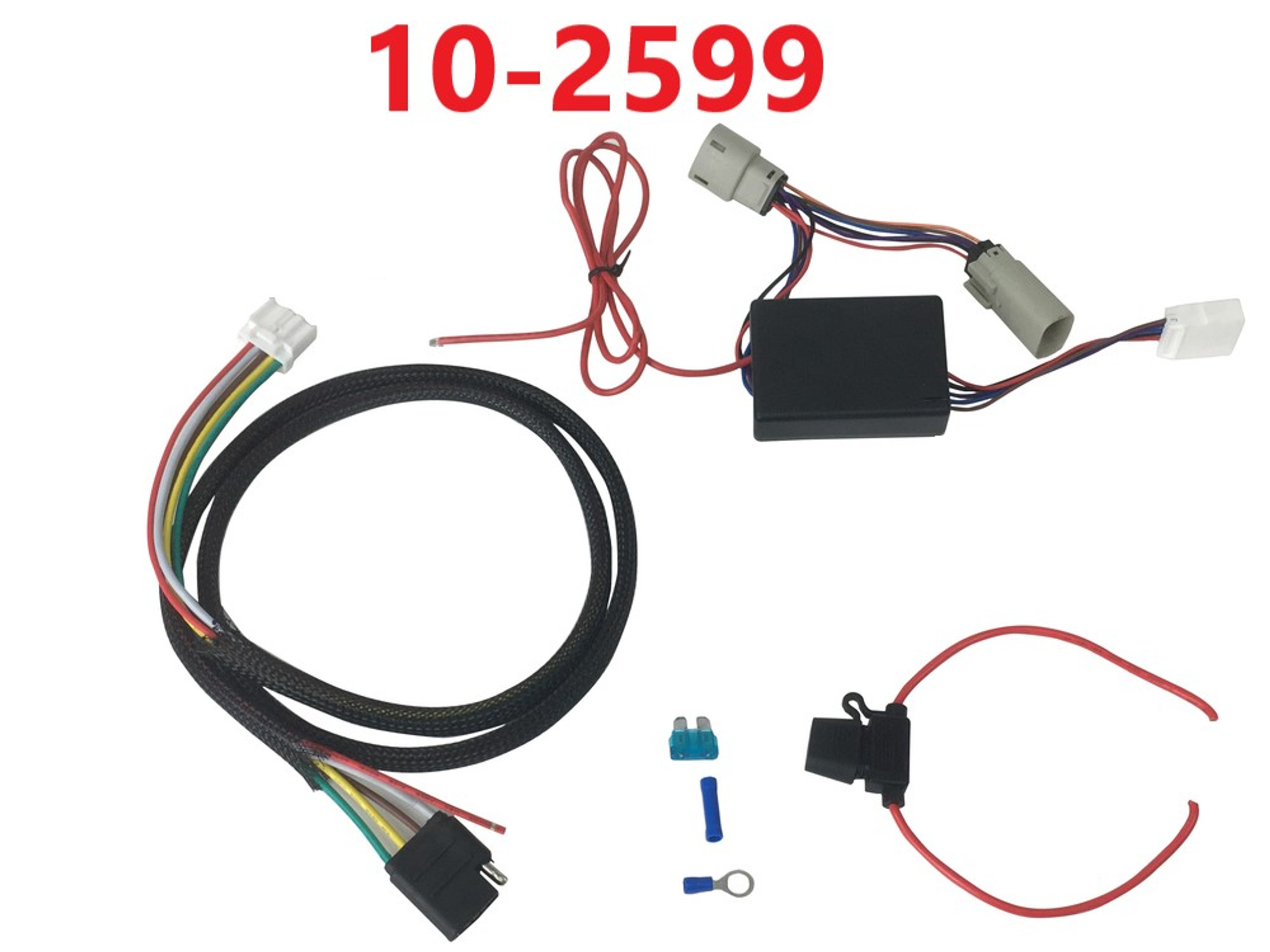
- Vehicle-Specific Connector: This is the “plug” part of “plug and play.” It connects directly into a factory-installed wiring port on your vehicle, typically located near the rear bumper. These connectors are designed to be keyed, meaning they only fit one way, preventing incorrect connections.
- Trailer Connector: This is the connector that plugs into the trailer's wiring. The most common types are:
- 4-Way Flat Connector: Provides basic lighting functions: running lights, left turn signal, right turn signal, and ground. Commonly used for smaller trailers.
- 5-Way Flat Connector: Adds a circuit for electric trailer brakes, often found on boat trailers with surge brakes.
- 6-Way Round Connector: Offers additional circuits, usually for backup lights or auxiliary power.
- 7-Way Round Connector (RV Blade Style): The most versatile connector, providing all the functions of the others, plus a dedicated 12V power circuit (often used for charging a trailer battery), and often a dedicated brake circuit. This is the standard for larger trailers and RVs.
- Wiring Harness: The bundle of wires that connects the vehicle-specific connector to the trailer connector. The wires are typically color-coded for easy identification.
- Control Module (Optional): Some vehicles, particularly those with complex electrical systems or LED lighting, require a control module. This module protects the vehicle's electrical system from overload and ensures proper operation of the trailer lights. It often includes short-circuit protection.
- Fuses: These are crucial safety devices that protect the wiring from overcurrent. If a circuit draws too much current, the fuse blows, breaking the circuit and preventing damage. Look for these usually inline, near the vehicle connector.
- Ground Wire: Usually a white wire, this is essential for completing the electrical circuit. It must be securely connected to the vehicle's frame or chassis.
Understanding Wiring Diagram Symbols
A wiring diagram is a visual representation of the electrical circuits in the harness. Understanding the symbols is key to deciphering the diagram:
- Lines: Represent wires. A solid line indicates a continuous wire, while a dashed line may indicate a wire that is connected through a connector or switch.
- Colors: Each wire is color-coded. Common colors include:
- Yellow: Left Turn/Stop
- Green: Right Turn/Stop
- Brown: Tail/Running Lights
- White: Ground
- Blue: Electric Brake (if applicable)
- Red: Auxiliary Power (12V+, if applicable)
- Connectors: Represented by various shapes, often circles or squares with numbers or letters indicating the pin number or function.
- Fuses: Depicted as a zigzag line inside a rectangle. The amperage rating is usually indicated next to the symbol.
- Ground Symbol: Typically three horizontal lines, resembling an inverted pyramid. This indicates a connection to the vehicle's chassis or frame.
How It Works
The basic principle is simple: the harness taps into the vehicle's existing lighting circuits and relays those signals to the trailer lights. When you activate the turn signal, the corresponding wire in the harness receives power and illuminates the trailer's turn signal light. The same applies to the brake lights and running lights.
Here's a simplified explanation of the process:
- The vehicle's lighting circuits send signals to the vehicle-specific connector.
- The harness transmits these signals through its color-coded wires.
- The signals reach the trailer connector.
- The trailer connector relays the signals to the corresponding lights on the trailer.
- The ground wire completes the circuit, allowing the lights to function properly.
If a control module is present, it acts as an intermediary between the vehicle's electrical system and the trailer lights. It monitors the current draw of the trailer lights and prevents overloads. It may also provide additional features, such as short-circuit protection and enhanced compatibility with LED trailer lights. Modern vehicles may use PWM (Pulse Width Modulation) to control the brightness of lights, which requires a more sophisticated control module to properly interface with the trailer lighting.
Real-World Use: Basic Troubleshooting Tips
Trailer light issues can be frustrating, but with a little knowledge, you can often diagnose and fix the problem yourself:
- No Lights at All:
- Check the vehicle's trailer wiring fuse(s).
- Inspect the ground connection for corrosion or looseness.
- Verify that the vehicle-specific connector is securely plugged in.
- Test the trailer connector with a multimeter to see if it's receiving power.
- One Light Not Working:
- Check the bulb in the affected light.
- Inspect the wiring and connectors for that specific light for damage or corrosion.
- Use a multimeter to check for voltage at the light socket.
- Erratic Lighting:
- Poor ground connection is the usual suspect. Clean and tighten the ground connection.
- Check for corroded connectors. Clean or replace them as needed.
Important: Always disconnect the trailer from the vehicle before troubleshooting the wiring. This will prevent accidental shorts and potential damage to the vehicle's electrical system.
Safety Considerations
Working with electrical systems always involves some risk. Here are a few key safety precautions to keep in mind:
- Disconnect the Battery: Before working on any electrical wiring, disconnect the negative terminal of the vehicle's battery. This will prevent accidental shorts and shocks.
- Use a Multimeter: A multimeter is an essential tool for diagnosing electrical problems. Use it to check for voltage, continuity, and resistance.
- Avoid Water: Never work on electrical systems in wet conditions. Water is an excellent conductor of electricity and can create a serious shock hazard.
- Proper Wire Connectors: Use appropriate wire connectors for making splices and connections. Avoid using household electrical tape, as it is not designed for automotive applications. Heat shrink tubing is preferred for creating a waterproof seal.
- Fuses are Crucial: Never bypass a fuse. If a fuse blows repeatedly, there is a problem in the circuit that needs to be addressed. Replacing a blown fuse with a higher amperage fuse can create a fire hazard.
- Control Modules: If your vehicle requires a control module, do not attempt to bypass it. These modules are designed to protect the vehicle's electrical system and ensure proper operation of the trailer lights.
Plug-and-play trailer wiring harnesses offer a convenient way to connect your trailer lights, but understanding the underlying principles is crucial for safe and reliable towing. By familiarizing yourself with the components, wiring diagrams, and troubleshooting tips, you'll be well-equipped to handle any challenges that may arise.
We have a detailed wiring diagram available for download. This diagram provides a visual representation of a typical 7-way round connector wiring harness, complete with color codes and pin assignments. Please contact us to access the file.