Polaris Ranger 1000 Fuse Box Diagram
Let's dive into the fuse box diagram for the Polaris Ranger 1000. Whether you're tackling electrical repairs, adding accessories, or just trying to understand your machine better, knowing your way around the fuse box is crucial. This guide will break down the diagram, explain the symbols, and provide practical troubleshooting tips to help you navigate the electrical system of your Ranger 1000 confidently.
Purpose of Understanding the Fuse Box Diagram
Why bother with a fuse box diagram? Simple: it's your roadmap to the electrical system. Here's what you gain by understanding it:
- Efficient Troubleshooting: When something electrical goes wrong (lights not working, winch failing, etc.), the fuse box is one of the first places you should check. The diagram helps you pinpoint the exact fuse related to the faulty component.
- Safe Modifications: Adding aftermarket accessories like lights, stereos, or winches requires tapping into the electrical system. Knowing the circuit load and fuse ratings prevents overloading circuits and potential damage or fire.
- Preventing Catastrophic Damage: Fuses are designed as the weak link in a circuit. They blow to protect more expensive components like the ECU (Engine Control Unit) or wiring harness from overcurrent. Understanding the fuse diagram means quicker identification and replacement, preventing further damage.
- General Understanding: For the DIY mechanic, understanding the fuse box diagram provides a deeper understanding of how all the electronic systems on the Ranger 1000 are connected and protected.
Key Specs and Main Parts of the Fuse Box
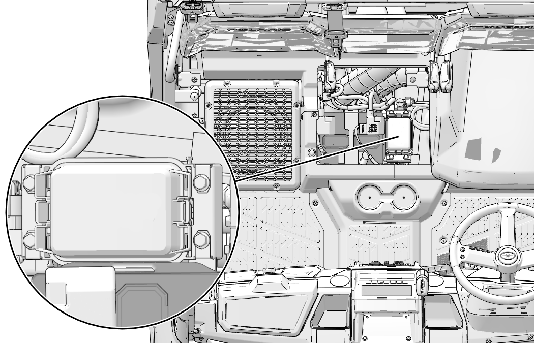
The Polaris Ranger 1000 fuse box is typically located under the hood, often near the battery. While the exact location can vary slightly depending on the model year, it's usually in an easily accessible area. Let’s talk about the specs and parts:
- Fuse Box Housing: This is the protective container for the fuses and relays. It's typically made of plastic and designed to shield the electrical components from moisture and debris.
- Fuses: These are the critical overcurrent protection devices. They contain a thin metal filament that melts and breaks the circuit when excessive current flows through it. Fuses are rated in amperes (amps or A), indicating the amount of current they can handle before blowing. Common fuse ratings in the Ranger 1000 include 5A, 10A, 15A, 20A, 25A, and 30A.
- Relays: Relays are electrically operated switches that control high-current circuits using a low-current signal. They are used to switch on things like headlights, fuel pump, and starter motor.
- Bus Bars/Power Distribution Blocks: These are conductive bars that distribute power from the battery to multiple circuits. They provide a central point for connecting fuses and relays.
- Fuse Puller: A small plastic tool included in the fuse box to safely remove and replace fuses. Using pliers can damage the fuse or surrounding components.
Fuse Types Commonly Used
The Ranger 1000 primarily uses blade-type fuses, also known as spade fuses. These come in two main sizes:
- ATO/ATC Fuses: Standard blade fuses.
- Mini Fuses: Smaller blade fuses used to save space.
Decoding the Symbols: Lines, Colors, and Icons
The fuse box diagram itself is a symbolic representation of the electrical system. Here's how to interpret the common symbols:
- Solid Lines: Represent wires or conductors. The thickness of the line doesn't typically indicate wire gauge on a fuse box diagram.
- Dotted Lines: Often indicate grounding paths or less critical circuits.
- Fuse Symbol: A zigzag line inside a rectangle. It indicates the location of a fuse and its corresponding amperage rating is usually printed nearby.
- Relay Symbol: Usually a square or rectangle with internal symbols representing the coil and contacts of the relay.
- Ground Symbol: Typically represented by three horizontal lines decreasing in length. It indicates a connection to the vehicle's chassis, providing a return path for the electrical current.
- Component Icons: The diagram will use icons or abbreviations to represent the components each fuse protects. For example:
- ECU: Engine Control Unit
- ECM: Engine Control Module
- EFI: Electronic Fuel Injection
- EPS: Electronic Power Steering
- Lights: Headlights, taillights, brake lights
- ACC: Accessory power
- FAN: Cooling fan
- Colors: Wiring diagrams (separate from the fuse box diagram) often use color-coding to identify individual wires. While the fuse box diagram itself may not be color-coded, knowing the common color codes for your Ranger 1000 can be helpful when tracing wires.
How the Fuse Box System Works
The fuse box acts as a central distribution point for electrical power and a protective barrier against overcurrents. Here's a simplified explanation of how it works:
- Power Source: The battery provides the primary source of electrical power.
- Distribution: Power flows from the battery to the fuse box, often through a main fuse or circuit breaker.
- Circuit Protection: Inside the fuse box, the power is distributed to various circuits, each protected by a fuse of the appropriate amperage rating.
- Component Operation: When a circuit is complete (e.g., you turn on the headlights), current flows through the fuse, then to the component, and back to the battery through the ground.
- Overcurrent Protection: If a short circuit occurs or a component draws excessive current, the fuse will blow, interrupting the flow of electricity and protecting the circuit from damage.
Real-World Use: Basic Troubleshooting Tips
Here's how to use the fuse box diagram for basic troubleshooting:
- Identify the Problem: Determine which electrical component is malfunctioning.
- Consult the Diagram: Locate the fuse on the diagram that corresponds to the faulty component. The diagram is usually printed on the inside of the fuse box cover.
- Inspect the Fuse: Use the fuse puller to remove the fuse and visually inspect it. A blown fuse will have a broken filament.
- Replace the Fuse: Replace the blown fuse with a new fuse of the same amperage rating. Never use a higher amperage fuse, as this can damage the circuit.
- Test the Component: Turn on the component to see if it now works.
- If the Fuse Blows Again: If the new fuse blows immediately, there is likely a short circuit or other problem in the circuit. Further diagnosis is required to find and fix the underlying issue. This might involve checking wiring, connectors, and the component itself.
Safety Considerations
Working with electrical systems can be dangerous. Here are some safety precautions:
- Disconnect the Battery: Before working on the fuse box or any electrical components, disconnect the negative battery cable to prevent accidental shorts or shocks.
- Use the Correct Fuse: Always replace a blown fuse with a fuse of the same amperage rating. Using a higher amperage fuse can overload the circuit and cause a fire.
- Avoid Moisture: Do not work on the fuse box in wet or damp conditions.
- Be Careful with Relays: Relays can be sensitive to static electricity. Handle them with care and avoid touching the pins unnecessarily.
- Seek Professional Help: If you are not comfortable working with electrical systems, consult a qualified mechanic.
High-Risk Components: The ECU and wiring harness are among the most expensive and sensitive components protected by the fuse box. Taking preventative measures to ensure proper fusing is crucial to protecting these components.
We have a high-resolution, downloadable fuse box diagram available for the Polaris Ranger 1000. This diagram will provide you with a detailed layout of the fuses and their corresponding functions, making troubleshooting even easier. Having this resource readily available will be invaluable for any electrical work you undertake on your Ranger 1000.