Polaris Sportsman 500 Starter Solenoid Wiring Diagram
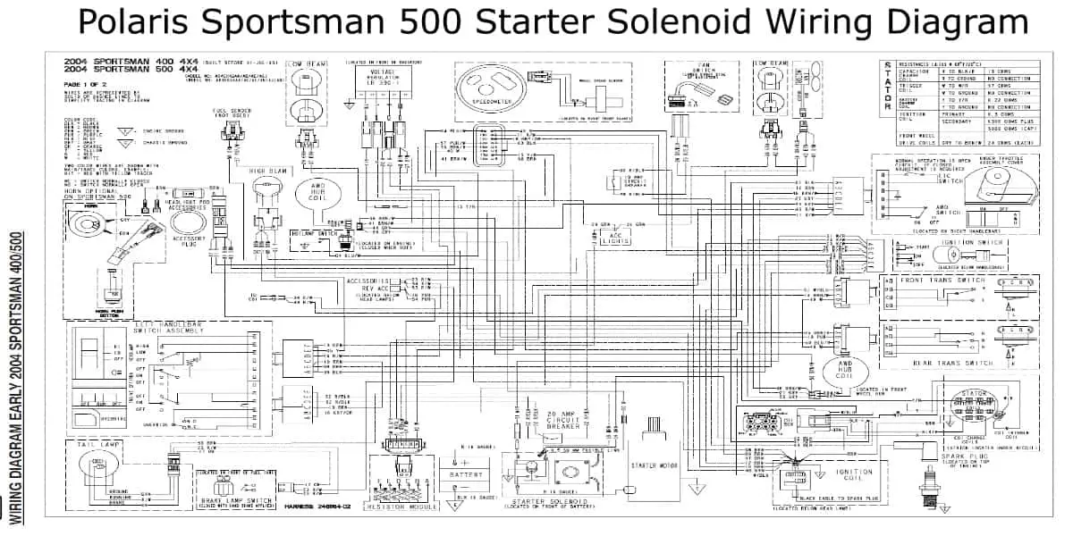
Let's dive deep into the Polaris Sportsman 500 starter solenoid wiring diagram. If you’re tackling electrical repairs, modifications, or just want to understand how your ATV’s starting system works, this guide will be your roadmap. Think of this as your trusted mechanic explaining it to you. We'll cover the essential parts, how they connect, and what those cryptic symbols actually mean.
Purpose of the Wiring Diagram
Why bother with a wiring diagram in the first place? Well, it's the key to unlocking your Sportsman 500's electrical mysteries. It allows you to:
- Diagnose electrical issues: Pinpoint problems within the starting circuit without blindly replacing parts.
- Perform repairs safely: Ensure you're connecting wires correctly, preventing shorts and further damage.
- Install accessories: Wire in aftermarket accessories like lights or winches with confidence.
- Understand the system: Grasp the flow of electricity and how each component contributes to the starting process.
Without a proper wiring diagram, you're basically operating in the dark – potentially causing more harm than good.
Key Specs and Main Parts
Before we dissect the diagram, let's identify the key players in the starting system. This is specific to the Polaris Sportsman 500, but the general principles apply to many ATVs and UTVs.
- Battery: The heart of the electrical system, providing the initial power. Typically a 12-volt DC battery.
- Ignition Switch: Controls the flow of electricity to various circuits when the key is turned.
- Starter Solenoid: An electromagnetic switch that handles the high current needed to power the starter motor. This is our focus here! It's critical because the ignition switch itself can't handle the large current required by the starter.
- Starter Motor: The device that physically cranks the engine, initiating the combustion cycle.
- Engine Ground: Provides a return path for the electrical current back to the battery. A solid ground connection is absolutely essential.
- Fuses: Safety devices that protect the electrical system from overloads.
- Wiring Harness: The network of wires that connects all the components.
The Starter Solenoid: Closer Look
The starter solenoid is basically a heavy-duty relay. It has two main circuits:
- Control Circuit: A low-current circuit that energizes the solenoid's electromagnet. This is triggered by the ignition switch.
- Power Circuit: A high-current circuit that connects the battery directly to the starter motor when the solenoid is activated.
Symbols – Deciphering the Diagram
Wiring diagrams use standard symbols to represent electrical components and connections. Learning these symbols is crucial for accurate interpretation.
- Solid Lines: Represent wires. The thickness may indicate the wire gauge (its current-carrying capacity).
- Dotted Lines: Often indicate connections that are part of a larger harness or are optional.
- Battery Symbol: Alternating long and short lines, indicating a DC power source.
- Switch Symbol: A break in a line, representing a switch that can open or close the circuit.
- Solenoid Symbol: A coil symbol with lines indicating the contacts it controls.
- Ground Symbol: Usually three horizontal lines decreasing in size, indicating a connection to the chassis or frame.
- Fuse Symbol: A zigzag line enclosed in a rectangle, representing a fuse.
- Color Codes: Wires are often color-coded (e.g., Red for power, Black for ground). The diagram will have a key identifying the color abbreviations.
Color coding is vital. Always double-check the color of the wire you're working with against the diagram to ensure you're connecting it correctly.
How It Works: The Starting Sequence
Here’s a step-by-step breakdown of how the starting system functions, according to the wiring diagram:
- Key Turn: When you turn the ignition key to the "start" position, a small amount of current flows from the battery, through the ignition switch, and to the starter solenoid's control circuit.
- Solenoid Activation: The current in the control circuit energizes the solenoid's electromagnet. This pulls a metal contact plate (the plunger) inside the solenoid.
- Power Circuit Connection: The plunger closes the high-current power circuit, connecting the battery directly to the starter motor.
- Starter Motor Engagement: The starter motor spins, engaging the engine's flywheel and cranking the engine.
- Engine Start: Once the engine starts, you release the key, the control circuit is de-energized, the plunger releases, and the power circuit is broken, stopping the starter motor.
The solenoid acts as a gatekeeper, preventing the high current from constantly flowing to the starter motor and protecting the ignition switch from damage.
Real-World Use: Basic Troubleshooting Tips
Here's how the wiring diagram can help you troubleshoot common starting problems:
- No Start, No Click: Check the battery voltage. Use a multimeter to ensure the battery is producing at least 12 volts. Trace the power wire from the battery to the ignition switch and then to the solenoid control circuit. A break in this circuit (blown fuse, faulty switch) will prevent the solenoid from activating.
- No Start, Clicking Sound: This often indicates a weak battery or a bad connection in the high-current power circuit. The solenoid is trying to engage, but the current isn't sufficient to turn the starter motor. Clean battery terminals, check the connections to the starter motor and the solenoid. Also could indicate a worn starter motor.
- Starter Motor Runs Continuously: This could indicate a stuck solenoid. The contacts inside the solenoid are fused together, keeping the power circuit closed even when the key is released. The solenoid needs to be replaced.
- Blown Fuses: Indicates a short circuit. Carefully inspect the wiring for damaged insulation or wires touching the frame. The wiring diagram will help you isolate the area where the short is occurring.
Always use a multimeter to test for voltage and continuity. This is the most reliable way to diagnose electrical problems.
Safety – Proceed with Caution
Working with electrical systems can be dangerous. Keep these safety points in mind:
- Disconnect the Battery: Before working on any electrical components, disconnect the negative terminal of the battery. This prevents accidental shorts and potential electrocution.
- Be Mindful of High-Current Circuits: The power circuit between the battery, solenoid, and starter motor carries a very high current. Accidental shorts in this circuit can cause fires and serious burns.
- Use Insulated Tools: Use tools with insulated handles to prevent electrical shock.
- Work in a Well-Ventilated Area: Batteries can produce hydrogen gas, which is flammable.
- Consult the Service Manual: Refer to the Polaris Sportsman 500 service manual for specific instructions and torque specifications.
The solenoid, and the wiring connected to it, carries significant amperage, making it a high-risk area for shorts and fires if mishandled.
By carefully studying the Polaris Sportsman 500 starter solenoid wiring diagram and following these guidelines, you'll be well-equipped to diagnose and repair starting system problems with confidence.
We have the complete Polaris Sportsman 500 Starter Solenoid Wiring Diagram file available for download to assist in any repairs or modifications.