Positive And Negative Battery Terminals Diagram
Understanding the positive and negative battery terminals is fundamental to any automotive work, from basic maintenance to complex electrical modifications. A diagram detailing these terminals isn't just a pretty picture; it's a vital tool that can save you time, prevent costly mistakes, and ensure your safety. This article dives deep into the anatomy of a battery terminal diagram, equipping you with the knowledge to interpret and utilize it effectively.
Purpose of a Battery Terminal Diagram
Why bother with a diagram? Several critical scenarios necessitate its use:
- Repairs and Maintenance: When replacing a battery, jump-starting a car, or working on the charging system, a diagram ensures you connect everything correctly. Reversing polarity can fry sensitive electronics.
- Electrical System Diagnosis: Tracing wiring issues, especially shorts or open circuits, often starts at the battery terminals. Knowing the intended connections is crucial for accurate troubleshooting.
- Modifications and Upgrades: Adding aftermarket accessories like amplifiers, lights, or auxiliary batteries requires tapping into the electrical system. A diagram helps you identify the appropriate connection points and ensure proper fusing.
- Learning and Understanding: For those new to automotive electrical systems, a diagram provides a visual representation of how the battery integrates into the overall circuit, fostering a deeper understanding of its role.
Key Specs and Main Parts
A typical battery terminal diagram focuses on the following components:
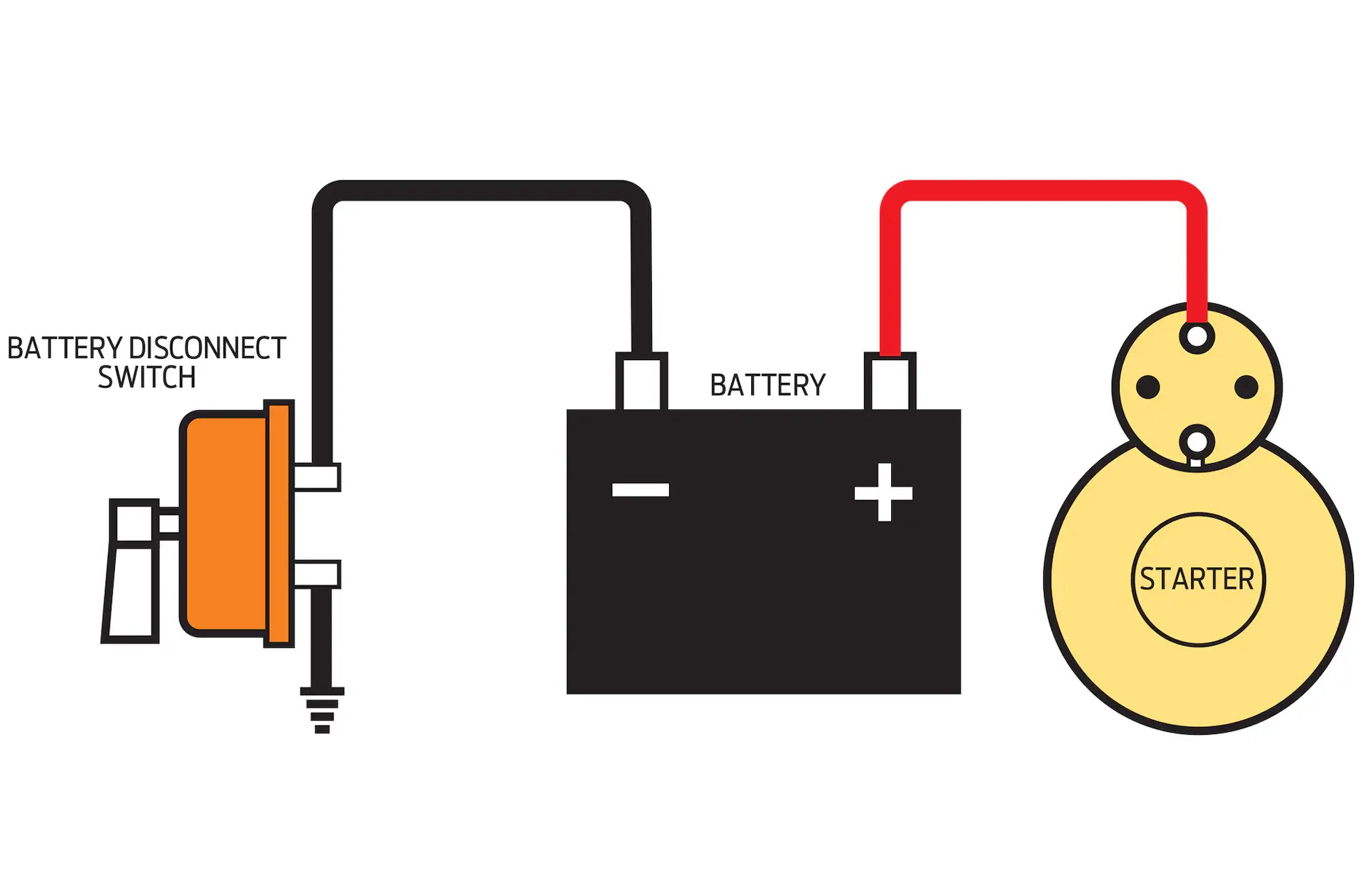
- Battery: Represented by a symbolic depiction – often a series of parallel lines denoting the individual cells.
- Positive Terminal (+): Usually larger in diameter and often marked with a "+" symbol or a red color. This is the terminal with a higher potential (voltage).
- Negative Terminal (-): Typically smaller than the positive terminal and marked with a "-" symbol or a black color. This terminal is often connected to the vehicle's chassis ground.
- Battery Cables: Heavy-gauge wires connecting the terminals to the vehicle's electrical system. The positive cable delivers power to the starter motor, alternator, and fuse box. The negative cable provides a return path for the current.
- Ground Connection: The point where the negative cable connects to the vehicle's chassis or engine block. This provides a common reference point (0 volts) for all electrical components.
- Fuses and Circuit Breakers: Often included in the diagram to show the protection circuits in place for various components powered by the battery.
Symbols: Lines, Colors, and Icons
Understanding the symbols used in a battery terminal diagram is essential for accurate interpretation:
- Solid Lines: Represent wires carrying electrical current. Thicker lines usually indicate higher current capacity.
- Dashed Lines: May represent wires hidden from view or wires with a different function, like a signal wire.
- Colors: Standard color coding is typically used. Red for positive connections and black for negative or ground connections. Other colors may represent specific circuits. Always refer to the diagram's legend if color coding is not immediately obvious.
- "+" and "-" Symbols: Clearly indicate the positive and negative terminals.
- Ground Symbol ( /\/\/\/\ ): Indicates the connection to the vehicle's chassis ground. This symbol may vary slightly depending on the diagram.
- Battery Symbol ( || || || ): Represents the battery. The longer line signifies the positive terminal, and the shorter line represents the negative terminal.
- Component Icons: Symbols representing other electrical components, such as fuses, relays, and starter motors, may also be included. These icons are typically standardized, but it's always a good idea to cross-reference them with a legend.
How It Works: The Electrical Circuit
The battery acts as the heart of the vehicle's electrical system. It provides the electromotive force (voltage) needed to power all electrical components. Current flows from the positive terminal, through the various circuits, and back to the negative terminal, completing the circuit.
Electromotive Force (EMF): The voltage produced by a battery or other power source. It's the "push" that drives the current through the circuit.
When you turn the ignition key, the starter motor draws a large amount of current from the battery. This current flows from the positive terminal, through the starter motor, and back to the negative terminal via the ground connection. The alternator then recharges the battery while the engine is running, replenishing the energy used by the starter and other electrical components.
Real-World Use: Basic Troubleshooting Tips
A battery terminal diagram can be invaluable for troubleshooting common electrical problems:
- Dead Battery: Check the connections at the terminals. Ensure they are clean and tight. Corrosion can significantly impede current flow. A voltmeter can be used to check the battery's voltage and confirm whether it needs charging or replacement.
- Slow Cranking: Similar to a dead battery, check the terminal connections and cable condition. A corroded or loose connection can restrict the current flow needed to crank the engine quickly.
- Electrical Component Malfunctions: If a specific electrical component is not working, use the diagram to trace the circuit back to the battery. Check for blown fuses or open circuits along the way.
- Parasitic Drain: If your battery is constantly draining when the car is off, a diagram can help you isolate the faulty circuit causing the drain. You can use a multimeter to measure current draw and then systematically disconnect circuits to identify the culprit.
Safety: Highlighting Risky Components
Working with automotive electrical systems can be dangerous. Always follow these safety precautions:
- Disconnect the Battery: Before working on any electrical components, disconnect the negative battery cable. This prevents accidental shorts and potential electrocution.
- Wear Safety Glasses: Batteries can leak corrosive acid. Protect your eyes from splashes.
- Avoid Sparks: Batteries produce hydrogen gas, which is highly flammable. Avoid creating sparks near the battery, especially when charging.
- Use Insulated Tools: Use tools with insulated handles to prevent accidental shorts.
- Be Aware of High Current: Batteries can deliver a significant amount of current, even at low voltage. Be careful not to short-circuit the terminals, as this can cause burns and damage to your tools.
The positive battery cable and the starter motor solenoid are particularly risky components due to the high current they carry. Exercise extreme caution when working near these components. Accidental contact with a grounded object while touching these components can result in severe burns or even death.
Understanding the positive and negative battery terminals and their associated wiring is crucial for maintaining and modifying your vehicle's electrical system. This detailed explanation, coupled with a clear diagram, provides you with the knowledge and confidence to tackle various automotive tasks safely and effectively.
We have a high-resolution, printable battery terminal diagram file available for download. This diagram will provide a visual reference to aid in your repairs and modifications. Please contact us if you would like to receive the link.