
Positive Crankcase Ventilation Diagram
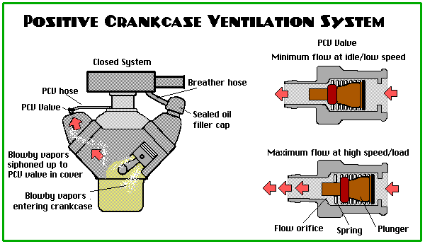
Okay, let's talk about Positive Crankcase Ventilation, or PCV. If you're diving into engine work, understanding the PCV system is crucial. It's not just some emissions control thing; it plays a vital role in engine health and performance. Knowing how it *should* work, and how to read a PCV diagram, is essential for diagnosing problems, making informed repairs, and even planning modifications. We've got a downloadable PCV diagram you can grab, and we'll walk you through how to understand it.
Why a PCV Diagram Matters
A PCV diagram is basically a roadmap for your engine's crankcase ventilation system. It shows you the location of all the components, how they connect, and how the system is supposed to function. Why does this matter?
- Troubleshooting: When you have oil leaks, rough idling, or other engine performance issues, the PCV system is often a prime suspect. A diagram helps you trace the system to identify blockages, leaks, or faulty components.
- Repairs: Replacing hoses, valves, or other PCV parts? The diagram makes sure you're connecting everything correctly and using the right parts.
- Modifications: If you're planning engine mods, especially forced induction (turbocharging or supercharging), you need to understand how the PCV system will be affected and how to modify it safely. A diagram is invaluable for planning these changes.
- Learning: Simply understanding how your engine works better allows you to diagnose problems. The PCV system is complex, and a diagram visually explains what's happening.
Key Specs and Main Parts
Before diving into the diagram itself, let's review the core components of a typical PCV system and their basic specifications.
- Crankcase: This is where the engine's crankshaft and connecting rods are located. It's also where combustion gases and oil mist can accumulate (blow-by).
- PCV Valve: This is the heart of the system. The PCV valve is a one-way check valve, usually spring-loaded, that regulates the flow of crankcase gases into the intake manifold. Its flow rate is crucial and must be matched to the engine's specifications. A typical spec is flow rate at a specific vacuum level.
- Vent Hose: This hose connects the crankcase to the air intake system, usually after the mass airflow sensor (MAF). It allows filtered air to enter the crankcase to replace the vented gases.
- Intake Manifold Connection: This is where the PCV valve connects to the intake manifold, allowing crankcase gases to be drawn into the engine and burned.
- Oil Separator (or Baffle): Located within the valve cover or intake manifold, this separates oil from the crankcase gases to prevent excessive oil consumption and fouling of the intake system.
Decoding the PCV Diagram: Symbols and Conventions
PCV diagrams use a variety of symbols to represent different components and connections. Here's a breakdown of common symbols:
- Solid Lines: Typically represent hoses or pipes carrying gases or fluids. The thickness of the line can sometimes indicate the hose diameter.
- Dotted Lines: Might indicate vacuum lines, or less critical connections. Also could indicate components that are present on some models, but not others.
- Arrows: Show the direction of airflow. This is *critical* for understanding how the system works.
- Colors: Colors might differentiate between different types of hoses (e.g., vacuum hose vs. coolant hose) or different stages of the PCV process. Consult the diagram's legend for specific color meanings.
- Component Icons: These are simplified drawings of the actual components. A rectangle with a zigzag line might represent the PCV valve. A circle with a filter icon could be the air filter for the vent hose.
Important: Always refer to the legend or key on the diagram to understand the specific symbols used. Different manufacturers may use slightly different conventions.
How It Works: A Step-by-Step Explanation
The PCV system's operation is relatively simple, but understanding the principles is key:
- Blow-by Gases: During combustion, some gases (unburned fuel, exhaust gases) leak past the piston rings and into the crankcase. These are called blow-by gases.
- Vacuum Draw: The engine's intake manifold creates a vacuum. The PCV valve is connected to the intake manifold.
- Controlled Ventilation: The PCV valve regulates the amount of crankcase gases drawn into the intake manifold. The amount the valve opens varies depending on manifold pressure and engine load. At idle (high vacuum), the valve restricts flow. At higher RPMs (lower vacuum), the valve opens more.
- Fresh Air Intake: As crankcase gases are drawn out, fresh, filtered air enters the crankcase through the vent hose connected to the air intake system. This creates a constant flow of air, purging the crankcase of harmful gases.
- Combustion: The crankcase gases, now mixed with fresh air, are drawn into the engine's cylinders and burned during normal combustion.
This closed-loop system prevents blow-by gases from venting directly into the atmosphere (which would be pollution) and helps maintain a slight vacuum in the crankcase, which improves piston ring sealing and reduces oil leaks. A blocked PCV system can result in increased pressure in the crankcase, causing gasket failure and oil leaks. A leaky PCV system (a hose off or cracked) can result in a vacuum leak and poor engine performance.
Real-World Use: Basic Troubleshooting Tips
Here's how you can use your knowledge of the PCV system and the diagram to troubleshoot common issues:
- Oil Leaks: Check for blocked or collapsed PCV hoses. A blocked PCV system can cause excessive pressure in the crankcase, leading to oil leaks from seals and gaskets. Also, check the oil separator for blockage.
- Rough Idling: A vacuum leak in the PCV system (e.g., a cracked hose or a stuck-open PCV valve) can cause a rough idle. Use the diagram to inspect all hoses and connections. A smoke test is ideal for diagnosing vacuum leaks.
- Excessive Oil Consumption: A faulty PCV valve or a clogged oil separator can allow excessive oil to be drawn into the intake manifold and burned, leading to increased oil consumption.
- Check Engine Light (CEL): Some PCV system failures can trigger a CEL. Scan the car for error codes. Common codes related to the PCV system include those for vacuum leaks, lean running conditions, or incorrect PCV valve flow.
Important: When diagnosing PCV problems, always start with a visual inspection of all hoses and connections. Look for cracks, leaks, and blockages. Then, check the PCV valve itself. You can often test it by shaking it – it should rattle. If it doesn't, it's likely stuck. Testing and diagnostics are always easier with the appropriate diagram.
Safety First: Risky Components
While the PCV system is generally safe, there are a few things to keep in mind:
- Hot Hoses: PCV hoses can get hot, especially those near the exhaust manifold. Allow the engine to cool down before working on the system.
- Flammable Gases: Crankcase gases contain flammable hydrocarbons. Avoid smoking or using open flames near the PCV system.
- Vacuum Leaks: As mentioned, a vacuum leak can cause a lean running condition, which can potentially damage the engine. Repair any leaks promptly.
- PCV Valve Contamination: Cleaning a PCV valve with solvents is generally *not* recommended, as the solvent can degrade the internal components. Replacement is usually the best option.
Disclaimer: Always consult your vehicle's repair manual for specific instructions and safety precautions. This article is for informational purposes only and should not be considered a substitute for professional advice.
Now that you have a solid understanding of PCV systems and how to interpret their diagrams, you're well-equipped to troubleshoot and maintain this important part of your engine. Remember, a healthy PCV system equals a healthier, longer-lasting engine.
We've created a detailed PCV diagram that is downloadable, so you can follow along and have a better understanding. This valuable resource allows you to quickly and easily find the components and connections.