Power Steering Rack And Pinion Diagram
Alright, let's dive into the power steering rack and pinion system. This article is your guide to understanding the diagram, its components, and how it all works together. Whether you're tackling a repair, planning an upgrade, or simply expanding your automotive knowledge, this breakdown will give you the confidence you need.
Why Understand the Power Steering Rack and Pinion Diagram?
A rack and pinion diagram isn't just a pretty picture; it's your roadmap for understanding and maintaining your vehicle's steering system. Knowing how to read and interpret it is crucial for several reasons:
- Diagnosis: Quickly identify the location of a faulty component. Is that leak coming from the high-pressure hose or the rack seal? The diagram helps pinpoint the source.
- Repair: Understand the proper sequence for disassembly and reassembly. This minimizes errors and prevents damage.
- Upgrades & Modifications: If you're considering upgrading to a performance rack or adding aftermarket components, you need to know where everything connects and interacts.
- Troubleshooting: Even if you're not a mechanic, knowing the layout helps you describe symptoms accurately to a professional.
- Learning: Gaining a deeper understanding of automotive systems is simply rewarding!
Key Specs and Main Parts of a Power Steering Rack and Pinion System
Before we delve into the diagram itself, let's identify the core components and some key specifications. Keep in mind that specifications will vary greatly based on vehicle make, model, and year.
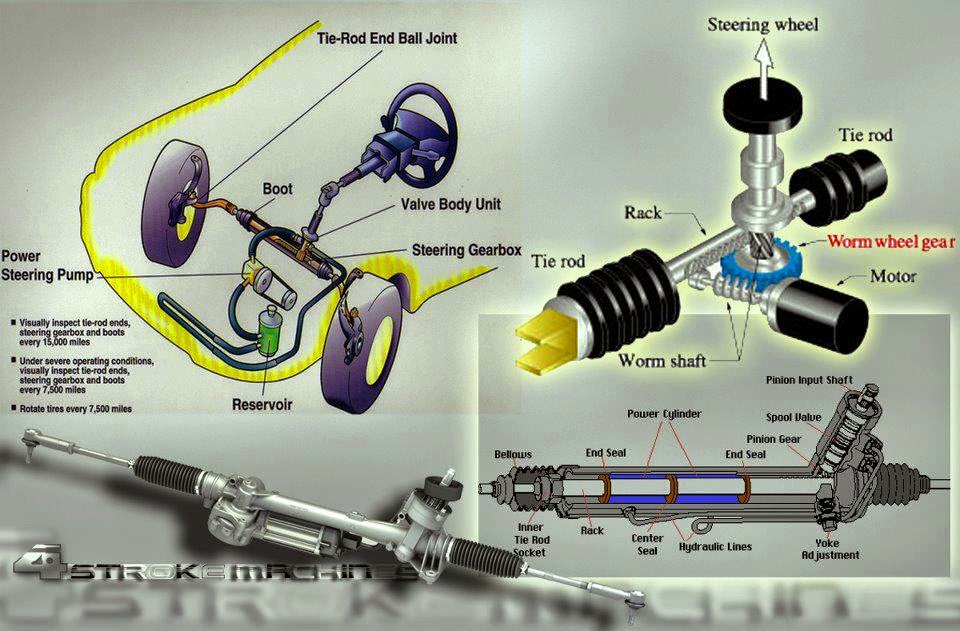
Main Components:
- Rack and Pinion Assembly: This is the heart of the system. The pinion gear (a small circular gear) meshes with the rack (a linear toothed bar). When you turn the steering wheel, the pinion rotates, moving the rack left or right.
- Power Steering Pump: Driven by the engine (usually via a belt), this pump creates hydraulic pressure.
- Hydraulic Hoses (High-Pressure and Low-Pressure/Return): These hoses carry the power steering fluid between the pump, the rack, and the reservoir.
- Reservoir: Stores the power steering fluid.
- Control Valve (Rotary Valve): Located within the rack and pinion assembly, this valve directs hydraulic pressure to either side of the rack, assisting your steering effort.
- Tie Rods (Inner and Outer): These connect the rack to the steering knuckles (the part that holds the wheel hub). They translate the rack's linear motion into the turning of the wheels.
- Steering Column: Connects the steering wheel to the pinion gear.
Key Specifications:
- Rack Travel: The total distance the rack can move from full left to full right. This affects the turning radius of the vehicle.
- Steering Ratio: The ratio of steering wheel rotation to wheel rotation. A lower ratio means quicker steering response (less steering wheel movement needed to turn the wheels).
- Pump Pressure: The amount of hydraulic pressure generated by the pump, usually measured in PSI (pounds per square inch).
- Fluid Type: The specific type of power steering fluid required by the system (e.g., Dexron III, Mercon V). Using the wrong fluid can damage the system.
Understanding the Symbols on the Diagram
Diagrams use standardized symbols to represent different components and connections. Here's a breakdown of common symbols you'll encounter:
- Solid Lines: Typically represent hydraulic lines carrying fluid under pressure.
- Dashed Lines: Often indicate vacuum lines or low-pressure return lines.
- Arrows: Show the direction of fluid flow.
- Circles: Can represent fittings, seals, or small components.
- Rectangles: May represent valves, pumps, or reservoirs.
- Component Labels: Each component will usually have a label (e.g., "PS Pump," "Rack Assembly").
- Color Coding (if present): Some diagrams use colors to differentiate between high-pressure and low-pressure lines, or different types of fluids.
Important Note: The legend or key is essential for interpreting any diagram. Always refer to it to understand the specific symbols and notations used in that particular diagram.
How the Power Steering Rack and Pinion System Works
Here's a simplified explanation of the system's operation:
- Turning the Wheel: When you turn the steering wheel, the steering column rotates the pinion gear.
- Valve Activation: The rotary valve senses the direction you're turning the wheel.
- Hydraulic Assistance: The rotary valve directs high-pressure fluid from the power steering pump to one side of the rack piston.
- Rack Movement: The hydraulic pressure assists the movement of the rack, making it easier to turn the wheels. If you're turning right, pressure is applied to the left side of the piston, pushing the rack to the right.
- Tie Rod Activation: The rack's movement is transferred to the wheels through the tie rods.
- Return Flow: Fluid from the opposite side of the rack piston returns to the reservoir.
Without power steering, you'd have to exert significantly more force to turn the steering wheel, especially at low speeds.
Real-World Use: Basic Troubleshooting Tips Using the Diagram
Here are a few common problems and how the diagram can help you troubleshoot them:
- Power Steering Fluid Leak: Use the diagram to trace the lines and identify potential leak points (hoses, fittings, rack seals). Pay close attention to connections.
- No Power Steering Assist: Check the pump, belt, and fluid level first. The diagram will show you the pump's location and how it's connected to the engine. If those are good, the problem could be the rotary valve or the pump itself.
- Noisy Power Steering: Often caused by low fluid or air in the system. The diagram shows the reservoir location so you can check the fluid level. Air can be introduced by leaks in the return lines or a faulty pump.
- Erratic Steering: This could be a problem with the control valve, the rack itself, or even worn tie rod ends. Use the diagram to visually inspect these components.
Remember: Always consult your vehicle's service manual for specific troubleshooting procedures and torque specifications.
Safety Considerations
Working on the power steering system involves potential hazards. Here are a few things to keep in mind:
- High Pressure: The power steering system operates under high pressure. Never disconnect hydraulic lines while the engine is running. Relieve pressure before disconnecting any lines.
- Fluid Hazards: Power steering fluid can be harmful. Wear eye protection and gloves to avoid contact with skin and eyes. Clean up any spills immediately.
- Hot Surfaces: The power steering pump and lines can get hot during operation. Allow them to cool before working on them.
- Jacking and Supporting: When working under the vehicle, always use jack stands to support it securely. Never rely solely on a jack.
- Proper Tools: Use the correct tools for the job. Using the wrong tool can damage components and increase the risk of injury. A flare nut wrench is crucial for hydraulic line fittings.
Replacing a power steering rack and pinion requires some mechanical aptitude and patience. If you're not comfortable with the procedure, it's best to have it done by a qualified mechanic.
You now have a solid understanding of the power steering rack and pinion system diagram and its significance. This knowledge will empower you to diagnose problems, perform basic maintenance, and even tackle more complex repairs. Remember to always consult your vehicle's service manual for specific procedures and safety precautions.
To further assist you, we have a downloadable file with a detailed power steering rack and pinion diagram. This diagram is yours to download. Click the link to access the file, and don't hesitate to use this resource as you delve deeper into understanding this vital automotive system.