Pressure Switch For Air Compressor Wiring Diagram
Alright, let's dive into pressure switch wiring diagrams for air compressors. If you're tackling repairs, modifications, or just trying to understand how your compressor ticks, grasping the wiring is crucial. This article aims to equip you with the knowledge to confidently interpret these diagrams, troubleshoot issues, and even perform basic wiring tasks. Consider this your in-depth guide to navigating the electrical heart of your air compressor.
Purpose of Understanding the Pressure Switch Wiring Diagram
Why bother learning this? Simple: troubleshooting. When your compressor isn't firing up, cycles erratically, or refuses to shut off, the pressure switch is a prime suspect. A wiring diagram provides the roadmap to diagnose issues, ensuring you're not just poking around blindly. It allows you to:
- Diagnose Electrical Problems: Identify faulty wiring, loose connections, or a malfunctioning switch.
- Perform Safe Repairs: Understand which wires to disconnect and reconnect safely.
- Upgrade or Modify Your System: Add accessories or upgrade components with confidence.
- Simply Understand Operation: Get a grip on how the electrical system functions as a whole.
Key Specs and Main Parts of a Pressure Switch
Before we crack the diagram, let's define the key components and their relevant specifications:
- Pressure Switch: The brains of the operation. It monitors air pressure in the tank and opens/closes electrical contacts to start or stop the motor.
- Cut-In Pressure: The pressure at which the switch *closes* the circuit, allowing the motor to start filling the tank. (e.g., 90 PSI)
- Cut-Out Pressure: The pressure at which the switch *opens* the circuit, stopping the motor. (e.g., 120 PSI)
- Differential: The difference between the cut-in and cut-out pressure. This prevents rapid cycling. (e.g., 30 PSI in the 90/120 example)
- Voltage and Amperage Rating: Crucial! The switch must be rated to handle the voltage and current draw of your motor. Pay attention to both AC (Alternating Current) and DC (Direct Current) ratings, if applicable.
- Number of Poles and Throws: Determines how the switch connects and disconnects circuits. Most common are Single Pole Single Throw (SPST) or Single Pole Double Throw (SPDT).
- Motor: Converts electrical energy into mechanical energy to drive the compressor pump. Its specifications (voltage, horsepower, amperage) dictate the requirements for the pressure switch and wiring.
- Wiring: Connects the pressure switch, motor, power source, and other components. Wire gauge (thickness) is crucial and must be appropriate for the amperage carried. Undersized wire can overheat and cause a fire.
- Overload Protection (Thermal Overload): A safety device built into the motor or a separate circuit breaker that trips if the motor overheats, preventing damage.
- Capacitor (If applicable): Some motors, especially single-phase motors, use capacitors to help with starting. These capacitors are often wired in series with the motor windings and are sometimes controlled by the pressure switch indirectly.
- Power Source: The electrical supply (typically 120V or 240V AC in North America).
Understanding Symbols in a Pressure Switch Wiring Diagram
Wiring diagrams use standardized symbols to represent components and connections. Here's a breakdown of common symbols you'll encounter:
- Lines: Solid lines represent wires. Dashed lines may represent mechanical linkages or less critical connections.
- Circles with Letters: Represent components. For example: 'M' for motor, 'PS' for pressure switch, 'OL' for overload.
- Switch Symbols: Show the state of the switch contacts. An open switch has a gap, indicating the circuit is broken. A closed switch has a continuous line, indicating the circuit is complete.
- Color Coding: While not universally standardized, common color codes are:
- Black: Usually indicates the hot (live) wire.
- White: Usually indicates the neutral wire.
- Green (or Bare Copper): Ground wire.
- Numbers/Labels: Identify terminals or connections. These are crucial for understanding where wires connect on the pressure switch and other components.
Think of the diagram as a map. It visually depicts how all the electrical components are interconnected. Understanding the symbols is like learning to read the map's legend.
How It Works: The Electrical Flow
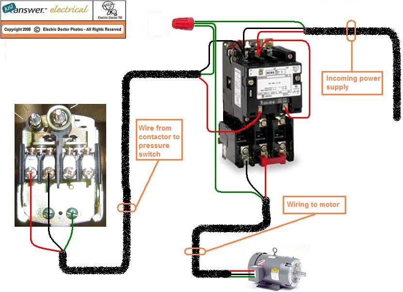
The pressure switch acts as an intermediary between the power source and the motor. Here's a simplified explanation of the typical electrical flow:
- The system starts with power coming from the electrical supply (e.g., 120V AC).
- The hot wire from the power source connects to the pressure switch.
- When the tank pressure is below the cut-in pressure, the pressure switch contacts close. This completes the circuit to the motor.
- Electricity flows through the pressure switch, through the motor windings (and potentially a capacitor), and back to the neutral wire (completing the circuit).
- The motor starts, driving the compressor pump to fill the tank.
- As the tank pressure rises, the pressure switch senses the increase.
- When the tank pressure reaches the cut-out pressure, the pressure switch contacts open.
- This breaks the circuit to the motor, stopping it.
- The motor remains off until the tank pressure drops below the cut-in pressure, at which point the cycle repeats.
- The ground wire provides a path for fault current to safely return to the source, tripping a breaker or fuse, protecting the equipment and people.
The pressure switch essentially automates the on/off function of the motor based on the air pressure in the tank.
Real-World Use: Basic Troubleshooting Tips
Here are a few common issues and how a wiring diagram can help diagnose them:
- Compressor Won't Start:
- Check for power: Verify the breaker hasn't tripped.
- Inspect the pressure switch: Use a multimeter to check if voltage is reaching the switch. If it is, and the tank pressure is below the cut-in point, the switch may be faulty. Check for continuity across the switch terminals when the switch should be closed.
- Check the motor overload: If tripped, allow it to cool down and reset. If it trips repeatedly, the motor may be overheating or drawing excessive current.
- Loose Connections: Use the wiring diagram to ensure all connections are secure.
- Compressor Won't Stop:
- Pressure switch malfunction: The contacts may be stuck closed. Replace the switch.
- Leaking tank/lines: If the compressor is constantly running to compensate for leaks, it may appear as though the switch is malfunctioning. Check for leaks first.
- Erratic Cycling:
- Incorrect pressure settings: The cut-in and cut-out pressures may be set too close together.
- Faulty pressure switch: Replace the switch.
Always disconnect the power supply before working on any electrical components.
Safety: Risky Components and Practices
Working with electricity can be dangerous. Here's what to be mindful of:
- Capacitors: Store a dangerous electrical charge even after the power is disconnected. Always discharge capacitors before handling them. Use a resistor (e.g., 20,000 ohm, 2-watt) to safely discharge the capacitor by connecting it across the capacitor's terminals.
- High Voltage: Air compressors often operate on 120V or 240V AC. This voltage can be lethal. Take extra precautions when working with these systems.
- Grounding: Ensure the compressor is properly grounded. This provides a safe path for fault current.
- Wire Gauge: Use the correct wire gauge for the amperage. Undersized wires can overheat and cause a fire. Consult a wiring chart to determine the appropriate gauge.
- Disconnect Power: Always disconnect the power supply before working on any electrical components. "Lockout/Tagout" procedures are essential in professional settings.
- Double-Check: Before reconnecting power, double-check all wiring connections to ensure they are secure and correct according to the diagram.
If you're uncomfortable working with electricity, always consult a qualified electrician.
By understanding the pressure switch wiring diagram and adhering to safety precautions, you'll be well-equipped to diagnose and repair common air compressor issues. Remember to work carefully, double-check your connections, and prioritize safety above all else. We have a detailed wiring diagram file available for download. Please contact us for access.