Pressure Switch For Water Pump Wiring Diagram
Alright, let's dive into understanding pressure switch wiring diagrams for water pumps. Whether you're grappling with a faulty well pump, planning a custom irrigation system, or just expanding your knowledge of practical electrical circuits, knowing how these switches work is invaluable. We're going to break down the diagram, explaining the components, how they interact, and troubleshooting tips to get you up and running.
Purpose of Understanding the Wiring Diagram
Why bother with a pressure switch wiring diagram? Here's the core reason: effective troubleshooting and repair. Without it, you're essentially poking around in the dark with live electricity – not a good idea! A diagram allows you to:
- Diagnose failures accurately: Identify if the pressure switch is the root cause of your pump problems.
- Perform repairs safely: Understand the circuit before disconnecting or replacing components.
- Customize your setup: Add features like low-pressure cutoffs or remote monitoring.
- Learn electrical basics: Gain a deeper understanding of how pumps and control systems operate.
Key Specs and Main Parts
Before we crack the diagram, let's define the essential components and their typical specifications. These specifications are examples, always check the manufacturer's specifications for your specific equipment.
- Pressure Switch: The heart of the system. It detects water pressure and opens or closes an electrical circuit based on pre-set thresholds. Common specs include:
- Pressure Range: e.g., 20-40 PSI, 30-50 PSI. This is the pressure at which the switch turns on and off the pump.
- Voltage Rating: e.g., 120VAC, 240VAC. The maximum voltage the switch can safely handle. Crucially important for safety.
- Amperage Rating: e.g., 10A, 20A. The maximum current the switch can safely carry. Make sure it exceeds the pump's running amps (RLA).
- Connection Type: e.g., NPT (National Pipe Thread). The size and type of threaded fitting used to connect to the water line.
- Water Pump: The device moving the water. You'll need to know its voltage and amperage requirements. A submersible pump is common in well systems, while booster pumps are used to increase water pressure in existing lines.
- Voltage: e.g., 120V, 240V, 3-phase.
- Horsepower (HP): e.g., 0.5 HP, 1 HP.
- Running Amps (RLA): The amount of current the pump draws when running at its designed load.
- Starting Amps: The very high current draw during the initial start-up of the pump. The wiring and switch needs to handle the surge.
- Pressure Tank: Stores water under pressure, reducing the frequency of pump starts and stops. This prolongs pump life.
- Wiring: Conductors carrying electricity. Proper gauge (thickness) is critical for safety and performance. Copper is most common.
- Circuit Breaker: A safety device that trips (disconnects) the circuit if an overcurrent situation occurs. It's essential for protecting the pump and wiring from damage.
- Amperage Rating:e.g., 15A, 20A. Needs to be sized appropriately for the pump.
Understanding Symbols in the Wiring Diagram
Wiring diagrams use a standardized set of symbols to represent electrical components and their connections. Here's a breakdown:
- Lines: Represent wires. Solid lines usually indicate conductors actively carrying current, while dashed lines *might* indicate control signals or grounding connections (depending on the specific diagram).
- Colors: Wire colors aren't always explicitly shown, but when they are, they adhere to a standard:
- Black: Hot (live) wire.
- White: Neutral wire.
- Green (or Bare Copper): Ground wire.
- Icons:
- Pressure Switch: Often depicted as a circle or rectangle with a switch symbol inside. The switch symbol indicates the contacts and their normal state (normally open or normally closed).
- Pump Motor: Usually represented by a circle with an "M" inside.
- Circuit Breaker: A stylized switch symbol with a line breaking through it.
- Ground: Typically a series of horizontal lines decreasing in size, connected to a single point.
Important Note: Always refer to the legend or key provided with the specific diagram you're using, as symbol conventions can vary slightly.
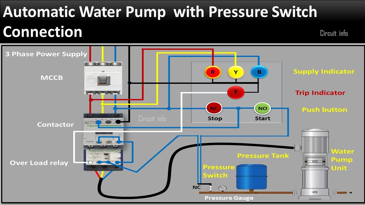
How It Works: The Circuit in Action
Here's the typical operational flow of a basic pressure switch controlled water pump system:
- Power Supply: Electricity enters the system from the main power panel, typically a 120V or 240V circuit.
- Circuit Breaker: The power passes through a circuit breaker for overload protection.
- Pressure Switch: The hot wire runs to the pressure switch. The pressure switch acts as a gate, allowing current to flow to the pump only when the water pressure is below the cut-in pressure (e.g., 20 PSI).
- Pump Activation: When the pressure drops below the cut-in point, the pressure switch closes, completing the circuit and energizing the pump motor.
- Pumping Water: The pump draws water from the source (well, tank, etc.) and pumps it into the pressure tank.
- Pressure Build-Up: As the tank fills, the water pressure increases.
- Pressure Switch Deactivation: When the pressure reaches the cut-out pressure (e.g., 40 PSI), the pressure switch opens, breaking the circuit and stopping the pump.
- Cycle Repeats: As water is used, the pressure in the tank drops, and the cycle repeats.
- Grounding: A crucial safety feature! The ground wire provides a low-resistance path back to the electrical panel in case of a fault (e.g., a wire touching the pump housing). This trips the circuit breaker, preventing electric shock.
A key point to note is the differential. The differential is the difference between the cut-in and cut-out pressures. A wider differential means the pump runs longer each cycle but starts less frequently.
Real-World Use: Basic Troubleshooting Tips
Here are a few common issues and how to approach them using the wiring diagram:
- Pump doesn't turn on at all:
- Check the circuit breaker – is it tripped? Reset it if necessary.
- Use a multimeter to verify voltage at the pressure switch. If no voltage, the problem is upstream (circuit breaker, wiring).
- If voltage is present at the pressure switch, check the switch contacts with a multimeter when the pressure is below the cut-in point. If the contacts are open (no continuity), the switch is likely faulty.
- Inspect the pump motor for damage.
- Pump runs constantly:
- Check for leaks in the plumbing system.
- The pressure switch might be stuck in the closed position. Inspect the switch and try to manually cycle it. If it's stuck, replace it.
- The pressure tank might be waterlogged (lacking air pressure). Check and adjust the air pressure in the tank.
- Pump cycles on and off rapidly (short cycling):
- This is often caused by a waterlogged pressure tank. Check and adjust the air pressure.
- A faulty pressure switch can also cause short cycling.
When troubleshooting, always disconnect power to the circuit before working on any components. Use a non-contact voltage tester to confirm that the circuit is de-energized.
Safety – Highlight Risky Components
Working with electricity is inherently dangerous. Always prioritize safety. The most significant risks involve:
- High Voltage: 120V or 240V electricity can be lethal. Always disconnect power before working on the circuit.
- Water and Electricity: Water conducts electricity. Never work on electrical components in wet conditions.
- Improper Wiring: Using undersized wiring or making loose connections can cause overheating and fire. Always use the correct wire gauge and ensure connections are secure.
- Grounding Issues: A properly grounded system is essential for safety. Never bypass or disconnect the ground wire.
- Capacitors: Some pump motors, especially those on larger pumps, use capacitors. Capacitors store an electrical charge, even when the power is disconnected. Discharge capacitors before handling them to avoid electric shock. Typically, discharging is done with a resistor.
If you are not comfortable working with electricity, consult a qualified electrician.
And that covers the basics of understanding a pressure switch wiring diagram for water pumps! By understanding the purpose, components, symbols, and operation of the circuit, you can troubleshoot issues, perform repairs, and even customize your setup with confidence. Remember to always prioritize safety and consult a professional when needed.
We have a sample wiring diagram file available for download, which can help you visualize these concepts. It includes annotations and clear labeling to guide you through the circuit.