Pulley Variable Speed Mtd Mtd Yard Machine Drive Belt Diagram
Alright, let's dive into the fascinating world of pulley variable speed drive belt diagrams for MTD, MTD Yard Machines, and similar lawn tractors. This isn't just about replacing a worn belt; it's about understanding the heart of your mower's speed control system. This knowledge empowers you to diagnose issues, perform repairs confidently, and potentially even make modifications to improve performance. We have the full diagram available for download, so you can follow along.
Purpose of the Drive Belt Diagram
Why bother with a diagram? Several reasons. Firstly, it's essential for accurate belt replacement. Incorrect belt routing is a common problem, leading to slippage, premature wear, and even complete system failure. Secondly, the diagram aids in troubleshooting speed control problems. Are you stuck in one speed, or is the speed inconsistent? The diagram helps you trace the power flow and identify potential culprits. Thirdly, for the adventurous DIYer, the diagram serves as a foundation for understanding the variable speed mechanism, which could lead to modifications or optimizations. Finally, a good diagram lets you perform the repair with confidence, knowing you have the correct information.
Key Specs and Main Parts
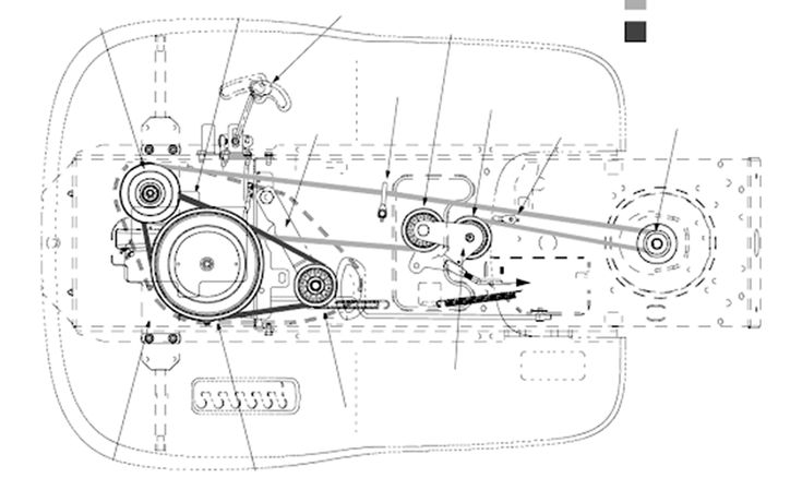
Before we get into the nitty-gritty, let's define the key components typically found in a variable speed pulley system on these machines. The exact configuration may vary slightly depending on the model, but the core principles remain the same:
- Engine Pulley (Driving Pulley): This pulley is directly connected to the engine's crankshaft. It provides the initial rotational force to the entire system.
- Variable Speed Pulley (Driven Pulley): This is the heart of the speed control. It's typically a split-sheave pulley (more on that later) that allows the effective diameter to change. This changes the gear ratio between the engine and the transmission.
- Transmission Pulley (Driven Pulley): This pulley is connected to the transmission input shaft. It receives the final rotational force from the variable speed pulley.
- Idler Pulley(s): These pulleys are strategically placed to maintain belt tension and guide the belt along the correct path. Some idler pulleys are spring-loaded to automatically adjust for belt stretch.
- Drive Belt: The V-belt itself is a critical component. It transmits power between the pulleys. Using the correct belt size and type is crucial. Check the diagram for the OEM (Original Equipment Manufacturer) part number.
- Speed Control Lever/Linkage: This lever, usually located near the driver's seat, controls the position of the variable speed pulley, effectively changing the speed.
- Springs & Linkages: These connect the speed control lever to the variable speed pulley. Ensuring these operate smoothly is essential for proper speed adjustment.
Diagram Symbols: Deciphering the Code
Understanding the symbols used in the drive belt diagram is crucial for interpreting the information it provides. Here's a breakdown of common symbols:
- Solid Lines: These generally represent the drive belt itself. The thickness of the line may sometimes indicate the belt width.
- Dashed Lines: These often represent linkages, cables, or other mechanical connections that are part of the speed control system.
- Arrows: Arrows indicate the direction of belt travel around the pulleys. Pay close attention to these! Incorrect belt routing will cause problems.
- Circles/Ovals: These represent the pulleys themselves. The size of the circle might indicate the relative diameter of the pulley.
- Small Circles with Crosshairs: These typically indicate pivot points or mounting locations for pulleys, linkages, or other components.
- Spring Symbols: These indicate the presence of a spring, which is often used to maintain belt tension or provide resistance in the speed control linkage.
- Part Numbers: Each component is typically labeled with a unique part number. This is essential for ordering replacement parts.
How It Works: The Variable Speed Magic
The magic happens in the variable speed pulley. This pulley is composed of two conical (tapered) discs (sheaves) that can move closer together or further apart. When the speed control lever is moved, it adjusts the distance between these sheaves. Here's how it affects the belt and the speed:
Smaller Effective Diameter: When the sheaves are close together, the belt rides higher up on the cones, effectively creating a smaller diameter for the pulley. This results in a lower gear ratio, meaning slower speed but higher torque.
Larger Effective Diameter: When the sheaves are further apart, the belt rides lower down on the cones, effectively creating a larger diameter for the pulley. This results in a higher gear ratio, meaning faster speed but lower torque.
The idler pulleys play a supporting role. By adjusting their position, the system maintains proper belt tension as the variable speed pulley changes diameter. A spring-loaded idler pulley is especially useful for automatically compensating for belt stretch over time.
Real-World Use: Troubleshooting Tips
Let's look at some common issues and how the diagram can help:
- Belt Slippage: If the belt is slipping, check for worn belts, incorrect belt routing, insufficient belt tension, or a seized pulley. The diagram will help you verify the correct belt routing and identify the tensioning mechanism.
- Stuck in One Speed: This could be due to a seized variable speed pulley, a broken linkage, or a stuck idler pulley. The diagram will help you trace the linkage from the speed control lever to the variable speed pulley and identify any potential binding points.
- Inconsistent Speed: This could be caused by a worn belt, a loose linkage, or a weak spring. The diagram will show you the location of all springs and linkages, allowing you to inspect them for wear or damage.
- Belt Coming Off: This is often caused by incorrect belt routing, a bent pulley, or a worn belt. The diagram will be essential for ensuring the belt is routed correctly.
When troubleshooting, always start with the simplest checks first: Is the belt properly routed? Is it the correct size? Is the tension correct? Only then should you move on to more complex issues.
Safety First!
Working on a lawn tractor can be dangerous if proper precautions aren't taken. Here are some key safety points:
- Disconnect the spark plug wire: Before working on any part of the engine or drive system, disconnect the spark plug wire to prevent accidental starting.
- Wear safety glasses: Protect your eyes from flying debris.
- Use jack stands: If you need to lift the tractor, always use jack stands to support it securely. Never rely on just a jack.
- Be aware of pinch points: The pulley system has many moving parts that can pinch fingers or hands. Keep your hands clear of these areas when the engine is running.
- The PTO (Power Take-Off) is a dangerous area. Never work around the PTO with the engine running, even if the PTO is disengaged.
The drive belt system, especially the PTO area, can be extremely dangerous if not handled with care. The rotating pulleys and belts can cause serious injury. Always be mindful of your surroundings and take necessary precautions.
With a solid understanding of the drive belt diagram and the components it represents, you're well-equipped to tackle common maintenance and repair tasks on your MTD, MTD Yard Machine, or similar lawn tractor. Remember to consult the diagram whenever you're working on the drive system, and always prioritize safety. Now, get that diagram downloaded and start fixing your machine!