Quadrajet Vacuum Line Diagram For Chevy 350
The Chevrolet 350 cubic inch (5.7L) small-block engine, especially when paired with a Quadrajet carburetor, is a legend in the automotive world. These engines were ubiquitous for decades, powering everything from family sedans to performance vehicles. Understanding the Quadrajet's vacuum system is crucial for proper operation, troubleshooting, and even performance modifications. This article will guide you through a typical Quadrajet vacuum line diagram for a Chevy 350, providing the knowledge you need to diagnose issues, make repairs, and ultimately, keep your classic running smoothly.
Purpose of Understanding the Quadrajet Vacuum Diagram
Why bother learning about a vacuum diagram? Several reasons come to mind:
- Restoration and Repair: Over time, vacuum lines crack, become brittle, or get disconnected. Knowing the correct routing is essential for restoring your engine to factory specifications.
- Troubleshooting: Vacuum leaks are a common cause of poor performance, rough idling, and emissions failures. A diagram helps you pinpoint the source of the leak.
- Performance Tuning: Understanding the vacuum system is fundamental for advanced carburetor tuning and performance modifications. You can optimize timing and fuel delivery for better power and efficiency.
- Learning Engine Fundamentals: Studying the vacuum system provides valuable insight into how an internal combustion engine operates, deepening your automotive knowledge.
Key Specs and Main Parts of the Quadrajet Vacuum System
The Quadrajet carburetor isn't just a single component; it's an integrated system reliant on vacuum to control various functions. Here's a breakdown of key elements:
- Carburetor Body: The main housing of the Quadrajet, containing the fuel bowls, throttle bores, and air bleeds.
- Vacuum Ports: These are small openings on the carburetor body that provide access to manifold vacuum or ported vacuum. Their location determines their function.
- Manifold Vacuum: Vacuum present below the throttle plates, always present and strongest at idle.
- Ported Vacuum: Vacuum present above the throttle plates, appearing as the throttle opens. It’s often used for emissions controls and spark advance.
- Throttle Plate: Controls the amount of air entering the engine.
- Choke: Restricts airflow to richen the mixture for cold starts.
- Vacuum Advance: A distributor advance mechanism that uses manifold or ported vacuum to advance the ignition timing based on engine load.
- EGR Valve (Exhaust Gas Recirculation): An emissions control device that recirculates exhaust gases back into the intake manifold to reduce NOx emissions. Controlled by vacuum.
- PCV Valve (Positive Crankcase Ventilation): Venting crankcase gases.
- Vacuum Canister (Charcoal Canister): Stores fuel vapors from the fuel tank and carburetor for later burning in the engine.
- Thermal Vacuum Switch (TVS): A temperature-sensitive switch that directs vacuum signals based on engine temperature.
Understanding the Vacuum Line Diagram Symbols
Vacuum diagrams use a standardized set of symbols to represent the various components and connections. Here's a breakdown of the most common ones:
- Solid Lines: Typically represent vacuum hoses.
- Dotted Lines: Often indicate capped vacuum ports or optional connections depending on vehicle configuration.
- Arrows: Show the direction of vacuum flow.
- Circles or Squares with Initials (e.g., EGR, PCV, DIST): Represent specific components like the EGR valve, PCV valve, or distributor vacuum advance.
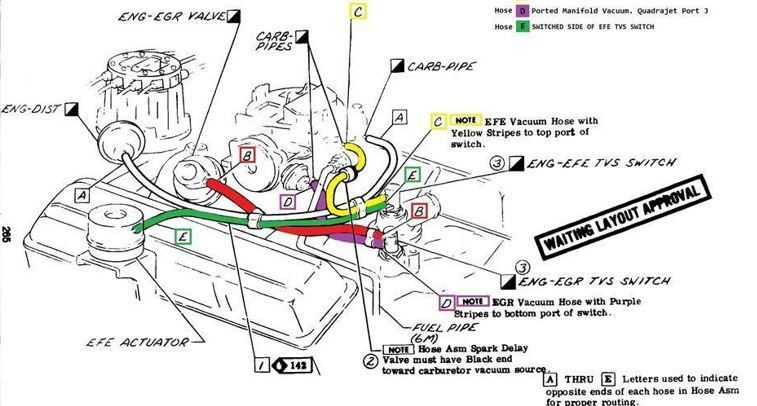
- Color Coding: Some diagrams use color coding to differentiate between vacuum sources and destinations. Common colors include black for manifold vacuum, green for ported vacuum, and red for connections to the charcoal canister. Note: Color coding isn't universally standardized.
- T-Fittings: Represent a vacuum line splitting into two or more branches.
- Check Valves: Allow vacuum to flow in only one direction, preventing backflow.
- Restrictors: Small orifices placed in vacuum lines to limit the rate of vacuum flow, often used in emissions control systems.
How the Quadrajet Vacuum System Works
The Quadrajet vacuum system utilizes manifold and ported vacuum to control several engine functions. Here's a simplified explanation:
- Idle Operation: At idle, the engine generates a strong manifold vacuum. This vacuum is used to operate the PCV valve, allowing crankcase gases to be drawn into the intake manifold and burned. Some vacuum is used to operate the vacuum break for the choke pull off.
- Part-Throttle Operation: As the throttle opens, ported vacuum becomes available. This ported vacuum is often used to control the distributor vacuum advance, improving fuel economy and throttle response. The EGR valve is also activated by ported vacuum under certain conditions, reducing NOx emissions.
- Acceleration: During acceleration, the vacuum signal changes rapidly. The Quadrajet uses these changes to meter fuel through the accelerator pump, providing a momentary rich mixture for smooth acceleration.
- Emissions Controls: The vacuum system is integral to the operation of various emissions control devices, such as the charcoal canister and EGR valve. These components work together to reduce harmful emissions from the engine.
Real-World Use: Basic Troubleshooting Tips
Vacuum leaks are a common problem in older vehicles. Here are some basic troubleshooting tips to help you diagnose and repair them:
- Visual Inspection: Carefully inspect all vacuum lines for cracks, breaks, or disconnections. Pay close attention to areas near heat sources or sharp edges.
- Vacuum Gauge: A vacuum gauge can be used to measure manifold vacuum. A low or fluctuating reading can indicate a vacuum leak.
- Spray Test: With the engine running, spray small amounts of carburetor cleaner or starting fluid around vacuum lines and connections. If the engine speed changes, you've likely found a vacuum leak. Be extremely careful when using flammable sprays near a hot engine.
- Listen for Hissing: A hissing sound can indicate a vacuum leak. Use a stethoscope or a length of hose to help pinpoint the source of the noise.
- Check Valve Operation: Ensure that check valves are functioning correctly, allowing vacuum to flow in only one direction.
Safety Precautions
Working with vacuum systems is generally safe, but there are a few precautions to keep in mind:
- Flammable Materials: Be extremely cautious when using flammable sprays like carburetor cleaner or starting fluid. Ensure the engine is cool and avoid spraying near ignition sources.
- Hot Surfaces: The engine bay contains many hot surfaces, such as the exhaust manifold. Avoid touching these surfaces to prevent burns.
- Moving Parts: Keep your hands and clothing away from moving parts, such as the fan and belts.
- Disconnect Battery: Disconnecting the negative battery cable before working on the electrical system is always a good safety practice.
The carburetor and its fuel lines represent the most significant fire risk within the vacuum system. Any fuel leaks coupled with an ignition source will create a fire risk. Exercise extreme caution to minimize this risk.
By understanding the Quadrajet vacuum line diagram and its function, you'll be well-equipped to maintain, troubleshoot, and even enhance the performance of your Chevy 350. Remember to take your time, be thorough, and prioritize safety. Armed with this knowledge, you can confidently tackle any vacuum-related issues that may arise.
We have a typical Quadrajet Vacuum Line Diagram file available for download, which can greatly assist in your repairs and understanding of the system.