
Rack And Pinion Power Steering Diagram
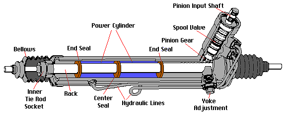
Let's dive into the world of rack and pinion power steering systems. This article will be your comprehensive guide, explaining the intricate details of a rack and pinion power steering diagram. Understanding this diagram is crucial whether you're diagnosing a fault, planning a repair, or simply expanding your automotive knowledge. We'll cover key components, symbols, how it all works, troubleshooting tips, and essential safety considerations. Plus, we have a downloadable diagram for your reference!
Why Bother with the Diagram?
A power steering diagram isn't just a pretty picture; it's your roadmap to understanding a complex system. Here’s why it's so valuable:
- Troubleshooting: When your steering feels off – heavy, loose, or noisy – the diagram helps you pinpoint the source of the problem. It allows you to trace the hydraulic or electrical circuits and identify potential faulty components.
- Repairs: Whether you're replacing a leaky hose, rebuilding the power steering pump, or swapping out the entire rack, the diagram provides the necessary context to ensure you're connecting everything correctly.
- Modification/Upgrades: Planning to upgrade your power steering system? Perhaps adding an aftermarket cooler or converting to an electric power steering (EPS) system? The diagram helps you understand the existing system's architecture and plan your modifications effectively.
- Learning and Understanding: Even if you're not currently facing an issue, studying the diagram allows you to deepen your understanding of automotive engineering and the intricacies of power steering systems.
Key Specs and Main Parts
Before we dissect the diagram itself, let’s define the key components of a rack and pinion power steering system. Keep in mind that configurations can vary slightly between vehicles, but the fundamental principles remain the same.
- Steering Wheel: This is where you initiate the steering action.
- Steering Column: Connects the steering wheel to the steering gear. It usually incorporates collapsible sections for safety in case of a collision.
- Steering Gear (Rack and Pinion): This is the heart of the system. The pinion is a small gear at the end of the steering column that meshes with the rack, a linear gear. As the pinion rotates, it moves the rack left or right.
- Tie Rods (Inner and Outer): These connect the rack to the steering knuckles (also called spindle) of the front wheels. The movement of the rack is translated into the turning motion of the wheels via the tie rods.
- Power Steering Pump: Driven by the engine (usually via a belt), the pump generates hydraulic pressure to assist the steering.
- Power Steering Reservoir: Holds the power steering fluid.
- High-Pressure Hose: Carries high-pressure fluid from the pump to the steering gear.
- Low-Pressure Return Hose: Returns the fluid from the steering gear back to the reservoir.
- Power Steering Cooler (Optional): Some vehicles, especially those subjected to heavy use or high temperatures, incorporate a cooler to prevent the fluid from overheating.
- Pressure Relief Valve: Protects the system from over-pressurization.
- Flow Control Valve: Regulates the amount of fluid flowing to the steering gear, providing consistent steering feel at different engine speeds.
- Rotary Valve/Solenoid Valve (Electronic Power Steering - EPS): In EPS systems, these components control the electric motor's assist based on sensor input.
Understanding the Symbols in the Diagram
The diagram uses standard symbols to represent the various components and their connections. Here's a breakdown of what you might encounter:
- Lines:
- Solid lines: Typically represent hydraulic lines (high and low pressure).
- Dashed lines: Often indicate electrical wiring or control signals.
- Dotted lines: May represent mechanical linkages or connections.
- Arrows: Show the direction of fluid flow or signal transmission.
- Color Coding: While not always present, color coding can further clarify the diagram:
- Red: Usually signifies high-pressure hydraulic lines.
- Blue: Typically represents low-pressure hydraulic lines.
- Black: Generally indicates ground wires.
- Other colors: May denote specific sensor signals or control circuits. Consult the diagram's legend for clarification.
- Component Symbols:
- Pump: A stylized representation of a pump, often with an arrow indicating the direction of fluid flow.
- Reservoir: A container symbol, sometimes with a level indicator.
- Rack and Pinion: A simplified depiction of the rack and pinion mechanism.
- Valve: A symbol representing a valve, with variations indicating different valve types (e.g., check valve, relief valve).
- Sensors: Symbols indicating various sensors, such as pressure sensors, torque sensors (in EPS systems), or speed sensors.
- Electric Motor (EPS): A symbol depicting an electric motor.
How It Works: The Power Steering Process
Let's trace the path of the power steering fluid and understand the sequence of events:
- Fluid Supply: The power steering pump draws fluid from the reservoir.
- Pressure Generation: The pump pressurizes the fluid and sends it through the high-pressure hose.
- Control Valve: The pressurized fluid reaches the control valve (rotary valve in hydraulic systems, solenoid valve in EPS systems) within the steering gear. This valve directs the fluid to either side of the rack based on the steering wheel input.
- Rack Assistance: If you turn the steering wheel, the valve directs fluid to one side of the rack's piston, assisting its movement. This reduces the effort required to turn the steering wheel.
- Return Flow: The fluid from the other side of the rack's piston flows back to the reservoir through the low-pressure return hose.
- Cooling (Optional): In some systems, the fluid passes through a cooler before returning to the reservoir.
- EPS Variations: In an EPS system, sensors detect the torque applied to the steering wheel and the vehicle's speed. This information is fed to a control module, which then commands the electric motor to provide the appropriate amount of assist.
Real-World Use: Basic Troubleshooting
Here are some common power steering problems and how the diagram can help:
- Hard Steering:
- Possible Cause: Low fluid level, faulty pump, blocked hose, malfunctioning control valve.
- Diagram Use: Trace the fluid flow path to identify blockages or leaks. Check the pump and control valve for proper operation using test points indicated on the diagram.
- Noisy Steering (Whining or Groaning):
- Possible Cause: Low fluid level, air in the system, worn pump.
- Diagram Use: Check the reservoir and hoses for air leaks. Identify the pump location to inspect for wear or damage.
- Leaking Fluid:
- Possible Cause: Damaged hoses, leaking seals in the pump or rack.
- Diagram Use: Identify the hose connections and potential leak points. The diagram can show the location of seals within the pump and rack.
- Erratic Steering (EPS systems):
- Possible Cause: Faulty torque sensor, malfunctioning control module, wiring issues.
- Diagram Use: Identify the location of the torque sensor and control module. Trace the wiring harness for breaks or shorts. Consult the diagram for diagnostic test points.
Safety First!
Working on power steering systems involves certain risks. Always observe these safety precautions:
- High Pressure: Power steering systems operate at high pressures. Never disconnect a hose while the engine is running or the system is pressurized. Serious injury can result from fluid injection.
- Hot Fluid: The fluid can get very hot. Allow the system to cool down before working on it.
- Eye Protection: Wear safety glasses to protect your eyes from fluid splashes.
- Proper Disposal: Dispose of used power steering fluid properly. It's considered hazardous waste.
- Disconnect Battery (EPS): When working on EPS systems, disconnect the battery to prevent accidental activation of the electric motor.
- Support the vehicle properly: when working under the vehicle use jack stands. Never rely only on the jack.
Having a comprehensive understanding of your vehicle's power steering system, aided by a detailed diagram, will make troubleshooting, repairs, and upgrades significantly smoother and safer. Remember to consult your vehicle's specific service manual for the most accurate and detailed information.
We have the rack and pinion power steering diagram file ready for you to download. It will serve as a valuable reference tool for your future automotive endeavors. Please remember to always prioritize safety and consult with a qualified mechanic if you're unsure about any aspect of the repair process. Good luck!