Radiator Electric Fan Wiring Diagram
Understanding your radiator electric fan wiring diagram is crucial for a variety of reasons. Whether you're troubleshooting a cooling system malfunction, upgrading to a higher-performance fan, or simply expanding your automotive knowledge, the diagram provides a roadmap to the electrical components and their interconnections. This article will delve into the specifics of a typical radiator electric fan wiring diagram, equipping you with the knowledge to interpret and utilize it effectively.
Purpose of a Radiator Electric Fan Wiring Diagram
The primary purpose of the radiator electric fan wiring diagram is to illustrate the electrical circuit that controls the fan's operation. This visual representation is invaluable for:
- Troubleshooting: Identifying faulty components (relays, sensors, wiring) when the fan fails to operate correctly.
- Repair: Replacing damaged wiring or components with the correct parts.
- Modification: Upgrading to a different fan, installing a manual override switch, or integrating the fan into an aftermarket engine management system.
- Understanding: Gaining a deeper understanding of how the cooling system functions.
Key Specs and Main Parts
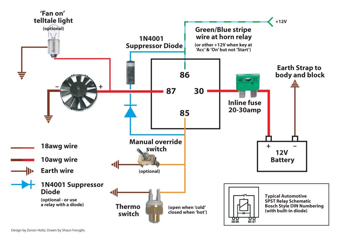
A typical radiator electric fan circuit includes the following key components:
- Electric Fan Motor: The actual fan that draws air through the radiator to cool the engine coolant. These are typically 12V DC motors, and their current draw can vary significantly based on size and design.
- Coolant Temperature Sensor (CTS): This sensor, often a thermistor, measures the engine coolant temperature and sends a signal to the ECU (Engine Control Unit) or a thermostatic switch. Its resistance changes with temperature.
- Engine Control Unit (ECU): The ECU, also sometimes referred to as a Powertrain Control Module (PCM), acts as the "brain" of the engine. It receives signals from various sensors, including the CTS, and controls various outputs, including the radiator fan relay.
- Relay: An electromagnetic switch that allows the ECU to control a high-current device (the fan motor) with a low-current signal. This protects the ECU from damage.
- Fuse: A safety device designed to protect the circuit from overcurrent. If the current exceeds the fuse's rating, it blows, interrupting the circuit and preventing damage to other components.
- Wiring: The conductors that connect all the components together. Wire gauge (thickness) is crucial to handle the current requirements of the circuit.
- Ground Connection: A secure connection to the vehicle's chassis, providing a return path for the electrical current. A poor ground can cause intermittent or complete failure of the fan.
Symbols – Lines, Colors, and Icons
Understanding the symbols used in the wiring diagram is essential for proper interpretation.
- Lines: Represent wires. The thickness of the line usually doesn't indicate wire gauge in a simplified diagram but pay attention to notes provided with the diagram.
- Colors: Each wire is typically color-coded. Standard automotive wiring color codes exist, but it's essential to refer to the specific vehicle's wiring diagram for accuracy. Common colors include red (power), black (ground), and various other colors for signal wires.
- Icons: Standardized icons represent various components:
- Fan Motor: Often depicted as a circle with a propeller inside.
- Relay: Typically shown as a square with a coil symbol and switch contacts.
- Fuse: Represented by a zig-zag line inside a rectangle.
- Ground: Usually a series of horizontal lines decreasing in size.
- Sensor: Can vary depending on the type of sensor, but generally a rectangle or circle with an arrow pointing inwards.
How It Works
The radiator electric fan circuit typically operates as follows:
- The Coolant Temperature Sensor (CTS) monitors the engine coolant temperature.
- The CTS sends a signal to the Engine Control Unit (ECU).
- When the coolant temperature reaches a pre-determined threshold, the ECU sends a low-current signal to the relay's coil.
- This energizes the relay's coil, causing the switch contacts to close.
- Closing the relay contacts completes the high-current circuit between the battery (or other power source) and the electric fan motor, through a fuse.
- The fan motor then turns on, drawing air through the radiator to cool the engine coolant.
- When the coolant temperature drops below another threshold, the ECU de-energizes the relay, opening the circuit and stopping the fan.
Some vehicles use a thermostatic switch instead of an ECU to control the fan. This switch directly controls the relay based on coolant temperature.
Real-World Use – Basic Troubleshooting Tips
Here are some basic troubleshooting steps when the radiator fan isn't working:
- Check the Fuse: A blown fuse is the most common cause of fan failure. Replace the fuse with one of the same amperage rating.
- Test the Relay: You can test the relay by swapping it with a known working relay (e.g., the horn relay, if it's the same type). You can also test the relay using a multimeter to check for continuity when the coil is energized.
- Inspect the Wiring: Look for any damaged, frayed, or corroded wiring. Pay particular attention to ground connections.
- Check the Coolant Temperature Sensor (CTS): Use a multimeter to check the sensor's resistance. Compare the resistance to the manufacturer's specifications for different temperatures. A faulty CTS can prevent the ECU from activating the fan.
- Verify ECU Output: Use a multimeter to check if the ECU is sending a signal to the relay when the engine is hot. If not, the ECU may be faulty or not receiving the correct input from the CTS.
- Test the Fan Motor Directly: Disconnect the fan motor connector and apply 12V directly to the motor terminals. If the fan doesn't run, the motor is likely faulty.
Safety – Highlight Risky Components
Working with electrical circuits can be dangerous. Always take the following precautions:
- Disconnect the Battery: Before working on any electrical component, disconnect the negative terminal of the battery.
- Use Proper Tools: Use insulated tools designed for automotive electrical work.
- Avoid Contact with Live Wires: Never touch exposed wires while the circuit is energized.
- Be Careful Around Moving Parts: Keep your hands and tools away from the fan blades when testing the fan.
- High-Current Circuits: The radiator fan circuit is a high-current circuit. Short circuits can cause severe burns and damage to the vehicle. Use caution when testing and troubleshooting.
Relays can get very hot when they are working, so avoid touching them immediately after operation.
Capacitors within the ECU or other modules can store a charge even after the battery is disconnected. Although rare, discharging these may be needed depending on your repair.
Understanding and carefully utilizing a wiring diagram is essential for diagnosing and repairing your radiator electric fan system. When in doubt, consult a qualified mechanic.
We have a detailed radiator electric fan wiring diagram file available for download. This diagram provides a comprehensive view of the circuit and will be an invaluable resource for your troubleshooting and repair efforts.