Radio Wiring Diagram For 2001 Chevy Silverado
Alright, let's dive into the radio wiring diagram for your 2001 Chevy Silverado. Whether you're dealing with a malfunctioning stereo, upgrading to a new head unit, or simply want to understand how the audio system works in your truck, this detailed guide will provide you with the knowledge and understanding you need. Think of this as your roadmap to navigating the electrical pathways of your Silverado's sound system. You can also download the complete diagram file from us.
Purpose and Importance
Why is understanding this diagram so important? Several reasons come to mind:
- Repairing a Faulty Stereo: If your radio is cutting out, has no power, or is exhibiting other strange behavior, the wiring diagram will help you pinpoint the source of the problem.
- Upgrading Your Head Unit: Installing a new aftermarket radio becomes much easier with a clear understanding of the existing wiring. You'll be able to connect the new unit correctly, avoiding potential damage.
- Adding Aftermarket Components: Planning to install an amplifier, subwoofer, or new speakers? The diagram will show you where to tap into the existing system for power and signal.
- Learning About Automotive Electrical Systems: Even if you're not currently experiencing any issues, studying the diagram is a great way to deepen your knowledge of automotive electrical systems in general.
Key Specs and Main Parts
Before we jump into the diagram itself, let's outline the key components and specifications involved in your 2001 Silverado's radio wiring:
- Head Unit: The central control unit of the audio system. This includes the radio tuner, CD player (if equipped), and the user interface.
- Speakers: Located in the doors, dash, or rear pillars, the speakers convert electrical signals into sound. Your Silverado likely has a 4-speaker system (two front, two rear).
- Antenna: Receives radio signals. The antenna is typically located on the roof or fender.
- Wiring Harness: A collection of wires bundled together, connecting the various components of the audio system. This is the key to navigating the system.
- Fuses: Protective devices that prevent damage to the electrical system in case of a short circuit. The radio will have its own fuse in the fuse box.
- Ground Connection: Ensures a proper return path for electrical current. A good ground is *crucial* for proper operation.
Important Electrical Specs to Consider:
- Voltage: The Silverado's electrical system operates at 12 volts DC.
- Wire Gauge: The thickness of the wires. Thicker wires can handle more current. The diagram will indicate the wire gauge for each circuit. This information is important if you're splicing or adding wires.
- Impedance: Measured in ohms (Ω), impedance affects how much current flows through the speakers. The impedance of the speakers should match the impedance that the head unit is designed to drive (typically 4 ohms). Mismatched impedance can damage the amplifier.
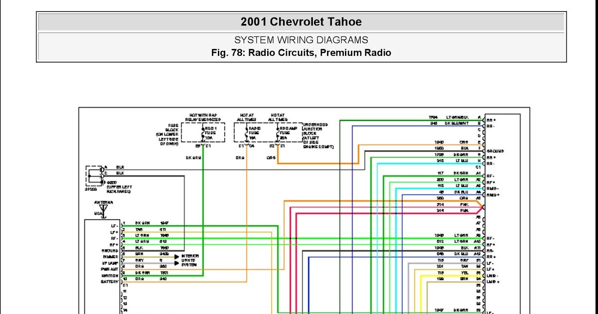
Understanding Symbols and Colors in the Diagram
The radio wiring diagram uses a variety of symbols, lines, and colors to represent different components and circuits. Let's break down some of the most common elements:
- Lines: Solid lines represent wires. Dashed lines may represent shielded cables or connections that are not always present depending on the vehicle configuration. The thickness of the line doesn't typically indicate wire gauge in these types of diagrams, but it's something to be aware of.
- Colors: Each wire is assigned a specific color code. The color code is critical for identifying the correct wire in the harness. Common colors include:
- Red: Typically power (12V+)
- Black: Ground
- Yellow: Constant power (for memory backup)
- Blue: Remote turn-on (for amplifiers)
- White/Gray/Green/Purple: Speaker wires (+ and -)
- Symbols:
- Resistors: Represented by a jagged line.
- Capacitors: Represented by two parallel lines.
- Ground: Represented by a downward-pointing arrow or a series of horizontal lines.
- Fuse: Depicted as a small rectangle with a line running through it.
- Connectors: Usually shown as circles or squares where multiple wires join together.
- Abbreviations: Expect to see abbreviations like "IGN" for ignition, "GND" for ground, "ACC" for accessory, and "AMP" for amplifier. The diagram legend will define all abbreviations.
How It Works: The Signal Path
Let's trace the signal path from the antenna to the speakers to understand how the radio system functions:
- Antenna: The antenna receives radio signals from broadcast stations.
- Head Unit: The radio tuner inside the head unit selects the desired station, amplifies the signal, and extracts the audio information.
- Amplification: The head unit contains a built-in amplifier that boosts the audio signal to a level suitable for driving the speakers. Some systems might have an external amplifier.
- Speaker Outputs: The amplified audio signal is sent to the speakers through the speaker wires.
- Speakers: The speakers convert the electrical signal into sound waves, which we hear as music or speech.
The power circuit is separate, supplying the head unit with the voltage it needs to operate. It usually involves two power sources: a constant 12V source (typically yellow) to retain memory settings, and a switched 12V source (typically red) that activates the head unit when the ignition is turned on. The ground wire (typically black) completes the electrical circuit.
Real-World Use: Basic Troubleshooting Tips
Here are some basic troubleshooting tips using the wiring diagram:
- No Power to Radio: Check the radio fuse in the fuse box. If the fuse is blown, replace it. If it continues to blow, there's likely a short circuit in the wiring. Use the diagram to trace the power wire from the fuse box to the head unit, looking for any signs of damage or exposed wires. Use a multimeter to test for voltage at the fuse and at the head unit.
- No Sound from Speakers: Check the speaker wires and connections. Make sure the speaker wires are properly connected to the head unit and the speakers. Use a multimeter to test the speaker wires for continuity. If one speaker is out, swap the speaker wires to isolate if it's a speaker problem.
- Poor Radio Reception: Check the antenna connection. Make sure the antenna cable is securely connected to the head unit. Inspect the antenna itself for damage.
- Ground Loops (Humming or Buzzing): Ground loops occur when there are multiple ground paths for the audio signal. Ensure that all ground connections are clean and secure. Consider using a ground loop isolator.
Always disconnect the negative battery terminal before working on the electrical system to prevent accidental shorts and potential damage.
Safety: Highlighting Risky Components
Working with automotive electrical systems can be dangerous if you're not careful. Here are some key safety considerations:
- Battery: The battery stores a significant amount of energy. Avoid short-circuiting the battery terminals, which can cause sparks, heat, and potentially an explosion.
- Airbag System: The airbag system is very sensitive. Do not tamper with the airbag wiring unless you are a trained technician. Disconnecting the battery for an extended period is always recommended to reduce the risk of accidental deployment, but this is not a guaranteed safe method. Consult a service manual before starting any work in proximity of airbag components.
- Short Circuits: A short circuit occurs when a wire comes into contact with ground. This can cause a large amount of current to flow, potentially damaging components or starting a fire. Always use proper wiring techniques and insulation to prevent short circuits.
Use a multimeter to test voltage and continuity before making any connections. Invest in quality wiring tools, such as wire strippers, crimpers, and connectors.
You can download the full radio wiring diagram for your 2001 Chevy Silverado from us. This detailed diagram will provide you with the precise wire colors and connector locations you need to successfully troubleshoot or upgrade your audio system.