Radio Wiring Diagram For 2001 Dodge Ram 1500
So, you're looking to tackle the radio wiring in your 2001 Dodge Ram 1500? Whether you're replacing a faulty unit, upgrading to a modern head unit with all the bells and whistles, or simply trying to diagnose a frustrating audio issue, understanding the radio wiring diagram is absolutely essential. This article will walk you through the intricacies of that diagram, equipping you with the knowledge to confidently navigate the electrical system of your truck's audio setup.
Purpose of Understanding the Radio Wiring Diagram
Why bother learning about a wiring diagram? Several reasons. First and foremost, it's your roadmap when performing any work on your truck's radio system. Without it, you're flying blind, risking damage to your electrical system, the new radio, or even yourself. Specifically, a wiring diagram is crucial for:
- Safe Radio Replacement: Ensure you connect the new radio's power, ground, speakers, and other functions to the correct wires in your truck's harness.
- Troubleshooting Audio Issues: Identify breaks in the wiring, short circuits, or malfunctioning components that are preventing your radio from working correctly.
- Adding Aftermarket Accessories: Integrate amplifiers, subwoofers, or other audio enhancements seamlessly without butchering your factory wiring.
- Understanding the System: Gain a deeper understanding of how your truck's audio system is designed and how its components interact.
Key Specs and Main Parts of the 2001 Dodge Ram 1500 Radio System
Before diving into the diagram itself, let's briefly touch on the key specifications and components commonly found in the 2001 Dodge Ram 1500's radio system. Keep in mind that variations can occur depending on trim level and factory options.
- Power Source: Typically, a 12-volt DC system powered by the truck's battery. This voltage is essential for powering the head unit and any connected amplifiers.
- Ground Connection: A dedicated ground wire provides a return path for the electrical current, ensuring the radio functions properly. This is often connected to the chassis of the vehicle for a reliable ground.
- Ignition Wire (Switched Power): Supplies power to the radio only when the ignition key is in the "Accessory" or "On" position. This prevents the radio from draining the battery when the truck is off.
- Constant Power (Battery Wire): Provides continuous power to the radio, even when the ignition is off. This allows the radio to retain memory settings, such as preset radio stations.
- Speaker Wires: These carry the audio signal from the radio to the speakers. There are typically four pairs of speaker wires: front left, front right, rear left, and rear right. Each pair consists of a positive (+) and a negative (-) wire.
- Antenna Wire: Connects the radio to the antenna, allowing it to receive radio signals.
- Factory Amplifier (If Equipped): Some models may have a factory amplifier, which boosts the audio signal before it reaches the speakers. If present, the wiring diagram will show the connections between the radio, the amplifier, and the speakers.
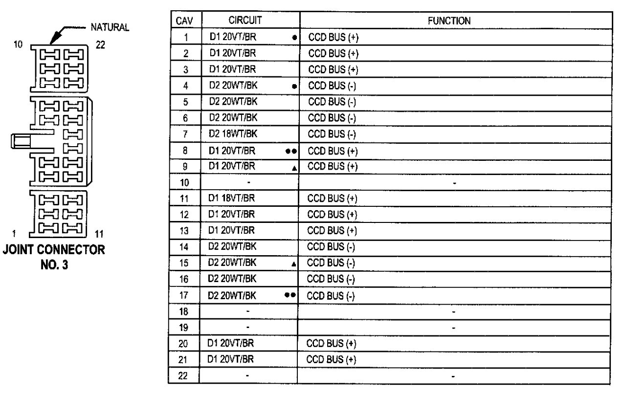
- Data Bus Connections (Possibly): Some higher-end models might have data bus connections (like Chrysler's PCI bus) which are used for communication between the radio and other vehicle systems. Aftermarket radio integration often requires adapters to correctly interpret and interface with these signals.
Symbols, Lines, Colors, and Icons in the Wiring Diagram
Understanding the symbols, lines, colors, and icons used in the wiring diagram is crucial for interpreting the information it conveys. Here's a breakdown of the common elements:
- Lines: Lines represent wires. The thickness of the line *doesn't* usually indicate the wire gauge.
- Colors: Each wire is typically identified by a color code (e.g., Red, Black, Blue/White). These color codes are critical for identifying the correct wires in your truck's harness. You'll often see abbreviations for the colors, such as "RED" for red, "BLK" for black, "BLU" for blue, "WHT" for white, "GRN" for green, and "YEL" for yellow. If a wire has a stripe, it will appear as "BLU/WHT" for a blue wire with a white stripe.
- Symbols: Specific symbols represent components such as:
- Resistors: Often shown as a jagged line or a rectangle.
- Capacitors: Usually two parallel lines.
- Ground: Typically three lines descending to a point, resembling an upside-down Christmas tree.
- Fuses: A small rectangle with a squiggly line inside.
- Connectors: Represented by circles or squares indicating a point where wires are joined. You'll also see connector numbers listed to help you locate the physical connectors in the vehicle.
- Wire Gauge: Although not always explicitly stated, wire gauge (thickness) can sometimes be inferred based on the amperage it carries. Speaker wires are typically thinner than power wires.
How It Works: Tracing the Circuit
The wiring diagram essentially shows the path of electrical current throughout the radio system. To understand how it works, trace the path of each circuit, starting from the power source (battery or ignition) and following it through the various components to the ground connection. For instance, you can trace the constant power wire from the battery, through a fuse, to the radio's memory circuit. Similarly, you can trace the speaker wires from the radio's output to each individual speaker.
Understanding the polarity is also important. Speaker wires always come in pairs, a positive and a negative. Getting these reversed will not damage your radio but could cause your speakers to be out of phase, which will degrade your sound quality. Many aftermarket radios and speakers mark these wires clearly, but the wiring diagram will also help you identify the correct polarity when connecting the speaker wires. Incorrect polarity can lead to weak bass response.
Real-World Use: Basic Troubleshooting Tips
Here's how you can use the wiring diagram for troubleshooting:
- No Power: If the radio isn't turning on, check the fuses first using a multimeter. Then, use the wiring diagram to trace the power and ground wires. Use a multimeter to verify that the radio is receiving 12V power on both the constant and switched power wires, and that the ground wire is properly grounded.
- No Sound: Check the speaker wires and connections. Ensure they are properly connected to both the radio and the speakers. Use a multimeter to check for continuity (a complete electrical path) between the radio's speaker output and the corresponding speaker. If there's no continuity, there's likely a break in the wire.
- Distorted Sound: Could be a faulty speaker, a loose connection, or a problem with the radio itself. Use the wiring diagram to isolate the problem. Try swapping the speaker connections to see if the distortion moves to a different speaker, which would indicate a problem with the original speaker.
Safety Considerations
Working with automotive electrical systems can be dangerous. Always disconnect the negative terminal of the battery before working on any electrical components. This will prevent accidental short circuits and potential electric shock. Be especially careful when working with the power and ground wires, as these carry a significant amount of current. Always use insulated tools and avoid working in wet conditions. Remember that airbags are also part of the electrical system and can be accidentally deployed if not handled correctly. Consult a professional if you're unsure about any aspect of the wiring.
Disclaimer
Warning: Automotive electrical systems can be complex and potentially dangerous. This information is provided for educational purposes only and should not be considered a substitute for professional advice. Always consult a qualified mechanic or electrician before attempting any repairs or modifications to your vehicle's electrical system.
With the knowledge you've gained here, you're well on your way to successfully working on your 2001 Dodge Ram 1500's radio wiring. Remember to take your time, double-check your connections, and prioritize safety. Good luck!