Radio Wiring Harness For 2012 Chevy Silverado
So, you're tackling the radio wiring in your 2012 Chevy Silverado? Whether you're upgrading to a fancy new head unit, troubleshooting a speaker issue, or just trying to understand how the factory system ticks, having a solid grasp of the wiring harness is essential. This isn't just about plugging things in; it's about understanding the flow of electricity, signal processing, and avoiding costly mistakes. Let's dive into the details. We have the complete wiring diagram available for download, which will be invaluable as you work through this.
Purpose: Decoding the Audio Network
Why bother with this level of detail? Well, a radio wiring diagram is your roadmap for all things audio in your Silverado. It serves several critical purposes:
- Upgrading Your Head Unit: Aftermarket stereos require adapting to the factory wiring. The diagram shows you exactly which wires to connect to your new stereo’s harness, ensuring proper functionality of speakers, power, ground, illumination, and other features.
- Speaker Replacement: If you're swapping out your factory speakers, the diagram identifies the correct speaker wires and polarity (+/-) to prevent phasing issues (where speakers cancel each other out, resulting in poor sound).
- Troubleshooting Audio Problems: No sound from a speaker? Intermittent static? The diagram helps you trace the signal path to pinpoint the source of the issue – a blown fuse, a short circuit, or a faulty component.
- Adding Aftermarket Amplifiers or Subwoofers: Understanding the wiring allows you to tap into the appropriate signal wires to feed your aftermarket amplifiers, ensuring proper signal levels and impedance matching.
- Learning Vehicle Electrical Systems: Even if you aren't currently working on your radio, studying the diagram is an excellent way to deepen your understanding of automotive electrical systems in general.
Key Specs and Main Parts
The 2012 Chevy Silverado radio system, while seemingly simple, is actually a complex network. Here's a breakdown of the core components you'll encounter in the wiring diagram:
- Head Unit: The brain of the operation. It receives signals, processes audio, and sends signals to the speakers. It also handles features like radio tuning, CD playback (if equipped), and potentially Bluetooth connectivity.
- Wiring Harness: A collection of wires bundled together, connecting the head unit to the vehicle's electrical system and speakers. This is where the wiring diagram becomes crucial. The harness includes wires for power, ground, speakers, accessory power (turns on with the ignition), illumination (dims with the headlights), and potentially other signals like steering wheel controls.
- Speakers: The output devices that convert electrical signals into sound. The Silverado typically has front and rear speakers, and potentially tweeters (smaller speakers for high frequencies) and a subwoofer (for low frequencies, depending on the trim level).
- Amplifier (if equipped): Some Silverado models (especially those with upgraded sound systems) have a separate amplifier that boosts the audio signal before it reaches the speakers. If present, the diagram will show the amplifier's location and wiring connections.
- GM LAN (Local Area Network): A digital communication network used in GM vehicles to transmit data between different modules, including the radio. The diagram may show connections to the GM LAN, especially for features like OnStar integration or steering wheel controls. This system use a CAN bus (Controller Area Network) to communicate.
- Antenna: Receives radio signals. The diagram will show the antenna connection to the head unit.
Decoding the Wiring Diagram: Symbols, Lines, and Colors
The wiring diagram uses a visual language to represent the electrical connections. Understanding these symbols is key to interpreting the diagram:
- Lines: Represent wires. The thickness of the line might indicate the wire's gauge (thickness), which relates to its current-carrying capacity. Thicker wires are used for power and ground, while thinner wires are used for signal connections.
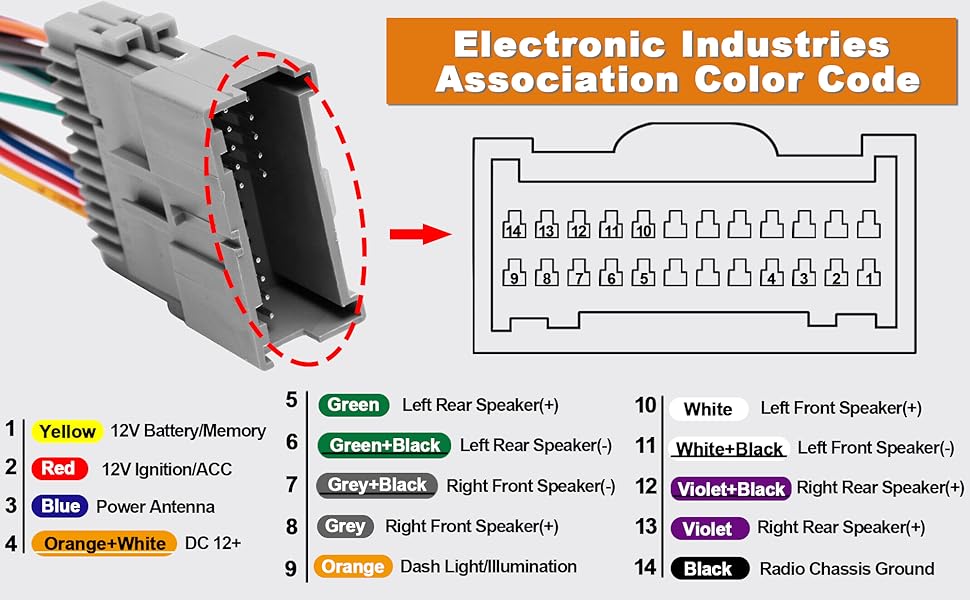
- Colors: Each wire has a specific color code (e.g., Red, Black, Yellow, Blue/White). The diagram will include a color code legend to identify the function of each wire. Accurate color identification is critical.
- Symbols:
- Circles: Represent connections or splices in the wiring.
- Rectangles: Represent components like fuses, relays, or connectors.
- Ground Symbol (typically a downward-pointing triangle): Indicates a connection to the vehicle's chassis ground.
- Speaker Symbol: A speaker cone symbol identifies speaker wires.
- Fuse Symbol: Represents a fuse, a safety device that protects the circuit from overcurrent.
- Connectors: The diagram will show the connector pinout, indicating which wire connects to each pin in the connector. Connector diagrams are crucial for identifying the correct wires in the harness.
- Abbreviations: Expect to see abbreviations like "ACC" (Accessory power), "GND" (Ground), "SPKR" (Speaker), "ILL" (Illumination), "BATT" (Battery power), and more.
Important Note: Variations in wiring can exist based on trim levels, options packages (like Bose audio), and even production dates. Always cross-reference the diagram with the actual wiring in your vehicle to ensure accuracy.
How It Works: The Audio Signal Path
The diagram reveals the flow of audio signals through the system:
- Source: The audio signal originates from the head unit (radio, CD, Bluetooth, etc.).
- Signal Processing: The head unit processes the audio signal, applying equalization, volume control, and potentially other effects.
- Amplification (if applicable): If an external amplifier is present, the signal is sent to the amplifier for further amplification. The amplifier boosts the signal power to drive the speakers.
- Speaker Output: The amplified signal is sent to the speakers, which convert the electrical signal into sound waves.
The wiring diagram shows the connections for each stage of this process, allowing you to trace the signal path and identify potential points of failure.
Real-World Use: Basic Troubleshooting Tips
Here's how to use the wiring diagram to diagnose common audio problems:
- No Power to the Head Unit: Check the fuses related to the radio. The diagram will show the location of the fuses. Use a multimeter to verify voltage at the power and ground wires going to the head unit.
- No Sound from a Speaker: First, check the speaker wires for loose connections or damage. Then, use a multimeter to test the speaker wire continuity from the head unit (or amplifier) to the speaker. If the continuity is good, the speaker itself may be faulty. Also, be certain the balance and fade are not set to exclude the speaker you are testing.
- Static or Distortion: Check the ground connections. A poor ground can introduce noise into the audio signal. Also, check for loose or corroded connectors.
- Steering Wheel Controls Not Working: This often involves the GM LAN. Ensure the connections to the GM LAN are secure. Aftermarket interfaces may be required to retain steering wheel control functionality with an aftermarket head unit.
Remember that an accurate multimeter is your best friend for electrical troubleshooting. Also, a basic understanding of automotive electrical principles is highly beneficial.
Safety First: Handling Risky Components
Working with automotive electrical systems can be dangerous. Here are some crucial safety precautions:
- Disconnect the Battery: Always disconnect the negative battery terminal before working on any electrical components. This prevents accidental short circuits and potential damage to the vehicle's electrical system.
- Identify Airbag Wires: Be extremely careful when working near airbag wiring. Accidental deployment of an airbag can cause serious injury. Consult the wiring diagram to identify airbag wires and avoid disturbing them.
- Use Proper Tools: Use insulated tools to prevent electrical shock. Ensure your multimeter is in good working condition and set to the correct range.
- Double-Check Your Work: Before reconnecting the battery, carefully double-check all your connections to ensure they are correct and secure.
Disclaimer: Working on automotive electrical systems can be complex and potentially dangerous. If you are not comfortable with electrical work, consult a qualified technician.
This guide is designed to provide a general overview. For complete troubleshooting and repair, referring to the actual wiring diagram for your 2012 Chevy Silverado is essential. The diagram contains vital information, including wire colors, connector locations, and circuit schematics that are specific to your vehicle.
We have the full wiring diagram available for you. With this diagram and the information provided here, you'll be well-equipped to tackle your Silverado's radio wiring with confidence.