Radio Wiring Mazda Wiring Diagram Color Codes
So, you're staring at a rat's nest of wires behind your Mazda's radio, ready to swap in a new head unit, fix a blown speaker, or just figure out why your sound system sounds like garbage. That's where a Mazda radio wiring diagram, especially understanding the color codes, becomes your absolute best friend. This isn't just a picture; it's your roadmap to electrical sanity. We're going to dive deep into how to read and use these diagrams, turning that intimidating tangle into something manageable.
Purpose of the Wiring Diagram
Why bother with a wiring diagram? Several reasons:
- Repairs: Pinpointing a short circuit, diagnosing a faulty speaker, or fixing a broken antenna connection becomes significantly easier with a diagram. Without it, you're just guessing.
- Upgrades: Installing a new head unit, amplifier, or subwoofer requires knowing which wire does what. Guessing can lead to expensive mistakes (fried electronics, anyone?).
- Learning: Understanding the flow of electricity through your car's audio system is a great way to expand your automotive knowledge.
- Modifications: Customizing your sound system, adding new features, or even diagnosing issues related to aftermarket installations relies heavily on proper wiring information.
Key Specs and Main Parts of the Diagram
Mazda wiring diagrams aren't all created equal. They can vary slightly depending on the model year and trim level of your car. However, some common elements remain consistent:
- Connector Views: These diagrams show the physical appearance of the connectors that plug into the back of the radio. They're crucial for identifying the correct pins.
- Wire Color Codes: This is the heart of the diagram. Each wire is assigned a specific color code (e.g., BLU for blue, RED for red, BLK for black). Sometimes you will find a combination of colors such as a main color and a stripe color (e.g., WHT/BLU for White with a Blue stripe)
- Component Symbols: Symbols represent different electrical components (radio, speakers, amplifiers, etc.).
- Circuit Paths: Lines on the diagram show the path of electricity from one component to another.
- Ground Points: Important for ensuring proper electrical grounding, indicated by a specific symbol.
- Fuses and Relays: Diagrams often show the location of fuses and relays that protect the radio circuit. Knowing where these are located and their function is critical for troubleshooting electrical issues.
Before you start, it's essential to get the correct diagram for your specific Mazda. Check your owner's manual, online forums, or a reputable service manual provider. Using the wrong diagram is worse than using no diagram at all.
Understanding Symbols, Lines, and Color Codes
Symbols
Electrical symbols are standardized, but let’s cover some you’ll commonly see in Mazda radio wiring diagrams:
- Resistor: Usually depicted as a zig-zag line.
- Capacitor: Two parallel lines, sometimes curved.
- Diode: A triangle pointing to a vertical line.
- Ground: Often shown as a series of downward-pointing lines, indicating a connection to the vehicle's chassis.
- Fuse: A small, squiggly line inside a rectangle, indicating an overcurrent protection device.
- Speaker: Usually looks like a stylized cone.
Lines
Lines in the diagram represent wires. A solid line usually indicates a direct connection, while a dashed line may indicate a shielded wire or a connection that exists only under certain conditions.
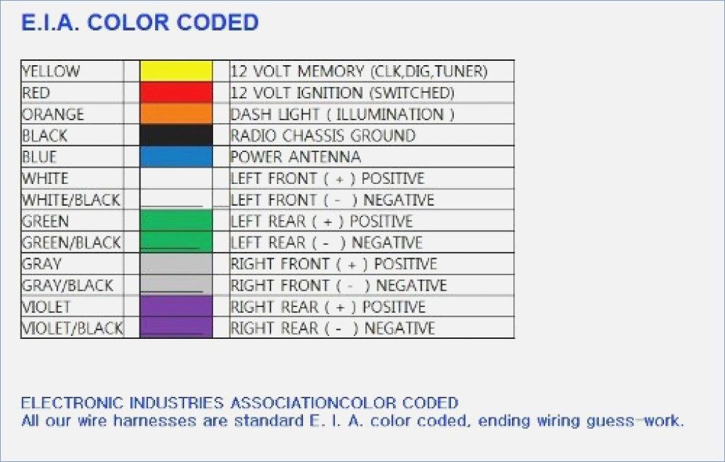
Color Codes
This is where the magic happens. Mazda, like most manufacturers, uses a standard color code for its wiring. Here’s a breakdown of some common colors you'll encounter:
- BLK (Black): Typically ground. Never assume this, always verify with the diagram.
- RED (Red): Usually a positive (+) power source, often direct from the battery.
- YEL (Yellow): Switched power, often from the ignition switch.
- BLU (Blue): Often used for the power antenna or amplifier remote turn-on.
- GRN (Green): Can be used for various purposes, including signal wires.
- WHT (White): Commonly used for speaker wires.
- BRN (Brown): Often used for accessories or illumination.
- ORG (Orange): Illumination circuit for dimming.
Important Note: Wire colors can sometimes vary depending on the specific model year and trim level. Always double-check the diagram for your vehicle.
How It Works: Tracing a Circuit
Let's say you want to trace the power supply to your radio. Start by identifying the power input wire on the radio connector view. The diagram will show this wire (usually red or yellow) connected to a fuse. Follow the line from the fuse to the battery or ignition switch. This shows you the path of the power supply. You can apply the same logic to trace speaker wires, ground connections, and other circuits.
The ability to trace circuits is crucial for troubleshooting. If your radio isn't turning on, you can use the diagram to check the power supply path, identify potential breaks in the circuit, and test the fuse and other components.
Real-World Use: Basic Troubleshooting Tips
Here are some common problems and how a wiring diagram can help:
- No Power to Radio: Use the diagram to check the power and ground connections. Use a multimeter to verify voltage at the power wire and continuity to ground. Check the fuses.
- Speaker Not Working: Trace the speaker wires from the radio to the speaker. Check for breaks or shorts in the wire. Test the speaker itself.
- Constant Battery Drain: A wiring diagram can help you identify parasitic draws. Disconnect the radio and see if the drain disappears. If it does, there's a problem within the radio circuit.
- Incorrect Wiring After Installation: Refer back to the wiring diagram to ensure each wire from the aftermarket head unit is connected to its corresponding wire in the vehicle's harness.
Pro Tip: When working on electrical systems, always disconnect the negative battery terminal to prevent short circuits and potential damage. Using a multimeter is essential for verifying voltage, continuity, and resistance.
Safety Precautions
Working with electrical systems can be dangerous. Here are some key safety precautions:
- Disconnect the Battery: As mentioned earlier, this is crucial to prevent accidental short circuits.
- Work in a Well-Lit Area: Good lighting makes it easier to see what you're doing and avoid mistakes.
- Use Insulated Tools: This will help protect you from electrical shock.
- Avoid Working with Live Wires: Only work with live wires if absolutely necessary and you have the proper training and equipment.
- Be Aware of Airbag Systems: Tampering with airbag wiring can be extremely dangerous. If you're unsure about anything, consult a professional.
- Capacitors Retain Charge: Be aware that capacitors in electronic components can retain a charge even after the power is disconnected. Discharge them safely before handling the components.
The most dangerous components are those related to airbag systems. Do not attempt to modify or repair these systems unless you are a qualified technician. Airbags can deploy unexpectedly and cause serious injury.
Final Thoughts
Understanding Mazda radio wiring diagrams and their color codes can seem daunting at first, but with a little practice, you'll be able to troubleshoot and upgrade your car's audio system with confidence. Remember to always prioritize safety, use the correct diagram for your vehicle, and double-check your work. With the proper knowledge and tools, you can tackle almost any audio-related project on your Mazda.
By familiarizing yourself with the concepts discussed, you can save money, gain valuable automotive knowledge, and enjoy a customized audio experience in your Mazda.
We have a high-resolution, downloadable Mazda radio wiring diagram file available. Feel free to reach out and we will provide the download.