Radio Wiring Subaru Wiring Diagram Color Codes
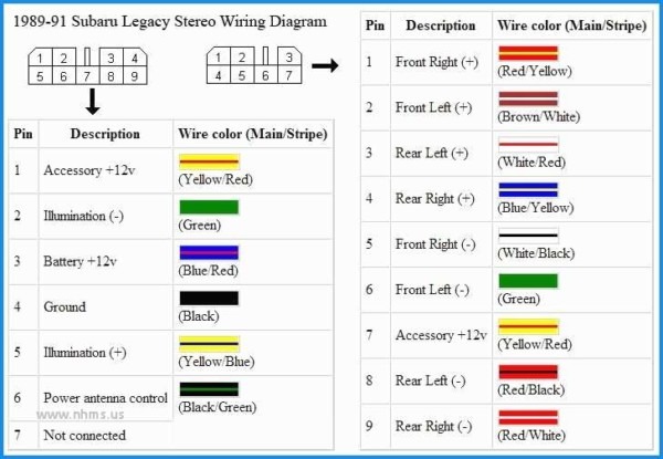
Radio wiring in a Subaru can seem like a daunting task, especially when faced with a multi-colored spiderweb of wires. Understanding the wiring diagram, including the color codes, is crucial for a successful installation, repair, or even upgrade of your car's audio system. Whether you're installing a new head unit, troubleshooting speaker issues, or simply curious about your car's electrical system, this guide will demystify Subaru radio wiring diagrams.
Purpose of the Radio Wiring Diagram
The Subaru radio wiring diagram serves as a roadmap for the entire audio system's electrical connections. Its primary purpose is to provide a visual representation of how the radio (or head unit), speakers, amplifier (if equipped), and other related components are interconnected. This diagram is invaluable for several reasons:
- Repair and Troubleshooting: When diagnosing audio problems, the wiring diagram helps you trace circuits, identify faulty connections, and pinpoint the source of the issue. For example, if a speaker isn't working, you can use the diagram to check the wiring continuity between the head unit and the speaker.
- Head Unit Installation: Installing an aftermarket head unit requires connecting it to the car's existing wiring harness. The wiring diagram shows you which wire controls which function (power, ground, speakers, etc.), allowing for a smooth and correct installation. Incorrect wiring can damage the head unit or the car's electrical system.
- System Upgrades: Planning to add an amplifier, subwoofer, or other audio components? The wiring diagram guides you in making the necessary connections without disrupting the existing system. It shows the pre-amp outputs, remote turn-on wires, and other connection points.
- Educational Purposes: Studying the wiring diagram is a great way to understand the overall electrical architecture of your car, especially the audio system. This knowledge can be helpful for future DIY projects or repairs.
Key Specs and Main Parts
A typical Subaru radio wiring diagram will include several key specs and depict the main parts of the audio system. Understanding these is vital for interpreting the diagram correctly.
- Voltage: Most Subaru audio systems operate on a 12V DC (Direct Current) system. This is important when selecting aftermarket components and connecting them correctly.
- Impedance: Speakers typically have an impedance of 4 ohms. Using speakers with a lower impedance than the head unit is designed for can damage the head unit. Always check the specifications before connecting speakers.
- Wattage: This specifies the power handling capacity of the speakers and the output power of the head unit or amplifier. Ensure your speakers can handle the output wattage of your head unit/amp.
Main components typically shown on a radio wiring diagram include:
- Head Unit (Radio): The central control unit for the audio system. It provides the signal source, volume control, and often includes an amplifier.
- Speakers: Front, rear, and sometimes center channel speakers, as well as subwoofers (if equipped).
- Amplifier (if equipped): An external amplifier provides additional power to the speakers, resulting in louder and cleaner sound.
- Wiring Harness: The connector that plugs into the back of the head unit, providing connections for power, ground, speakers, and other functions.
- Antenna: Receives radio signals.
Symbols – Explain Lines, Colors, and Icons
Understanding the symbols used in a wiring diagram is crucial for accurate interpretation.
Lines
- Solid Lines: Represent wires connecting components. The thickness of the line doesn't usually indicate wire gauge (though sometimes thicker lines represent higher current carrying wires).
- Dashed Lines: Often indicate shielded wires (used for signals that are sensitive to interference), or sometimes, connections within a single component or module.
Colors
Color codes are arguably the most important aspect of a wiring diagram. Each wire is assigned a specific color or a combination of colors. Common Subaru wire colors include:
- Red: Typically indicates a constant +12V power source. This wire is always "hot" and provides power even when the ignition is off.
- Yellow: Usually a switched +12V power source. This wire only provides power when the ignition is turned on.
- Black: Almost always represents ground (negative terminal).
- White: Often used for speaker wires, sometimes with a colored stripe.
- Green/Blue/Gray/Purple: Typically used for speaker wires.
It's crucial to consult the specific wiring diagram for your Subaru model and year, as color codes can vary slightly. Always verify the function of a wire before making any connections.
Icons
Common icons you might encounter include:
- Ground Symbol: Represents a connection to the chassis ground.
- Fuse Symbol: Represents a fuse in the circuit.
- Connector Symbol: Indicates a plug or connector where wires are joined.
- Speaker Symbol: Represents a speaker.
- Resistor Symbol: Represents a resistor.
How It Works
The audio system's basic functionality is as follows:
- Power Supply: The head unit receives power from two sources: a constant +12V (Red wire) and a switched +12V (Yellow wire). The constant power allows the head unit to retain memory (radio presets, settings, etc.), while the switched power turns the unit on and off with the ignition.
- Grounding: The head unit is grounded to the vehicle's chassis (Black wire). A good ground connection is essential for proper operation.
- Signal Generation: The head unit generates an audio signal from various sources (radio, CD player, auxiliary input, Bluetooth).
- Amplification: The head unit's internal amplifier (or an external amplifier) amplifies the audio signal.
- Speaker Output: The amplified signal is sent to the speakers via the speaker wires. Each speaker has two wires: a positive (+) and a negative (-). The wiring diagram will indicate the correct polarity for each speaker. Connecting speakers with reversed polarity can result in poor sound quality.
Real-World Use – Basic Troubleshooting Tips
Here are a few common troubleshooting scenarios and how the wiring diagram can help:
- No Power to Head Unit: Use a multimeter to check for voltage on the constant and switched power wires. If there's no voltage, check the corresponding fuses. If the fuses are good, trace the wiring back to the battery or ignition switch to identify the break. Also, check the ground connection. A bad ground can cause all sorts of problems.
- One Speaker Not Working: Use the wiring diagram to identify the speaker wires for the non-working speaker. Use a multimeter to check the continuity of the wires. If the wires are intact, the speaker itself may be faulty. You can also test the output from the head unit using another speaker to rule out head unit issues.
- Static or Noise: Check the ground connections. A loose or corroded ground can introduce noise into the audio system. Also, ensure that speaker wires are not running near sources of electrical interference, such as the engine control unit (ECU) or power wires.
Safety – Highlight Risky Components
Working with automotive electrical systems can be dangerous. Here are some safety precautions:
- Disconnect the Battery: Always disconnect the negative terminal of the battery before working on any electrical components. This prevents accidental short circuits and potential damage to the car's electrical system.
- Work in a Well-Lit Area: Proper lighting is essential for seeing the wiring diagram and the wires you're working with.
- Use Proper Tools: Use insulated tools designed for automotive electrical work. This includes wire strippers, crimpers, and multimeters.
- Be Careful with Fuses: Never replace a fuse with one of a higher amperage. This can overload the circuit and cause a fire.
- Airbags: Be aware of the location of airbags in your vehicle. Improper wiring or accidental shorts can trigger the airbags, causing injury.
Exercise extreme caution when working near airbag modules.
- Capacitors After disconnecting the battery, wait a few minutes before handling the head unit or amplifier. Capacitors inside these devices can hold a charge even after the power is disconnected, potentially causing a shock.
By understanding and utilizing the Subaru radio wiring diagram, you can confidently tackle audio system repairs, upgrades, and installations. Remember to always prioritize safety and consult the specific diagram for your vehicle's make and model. With a little patience and attention to detail, you'll be enjoying enhanced audio in your Subaru in no time!
We have a Subaru wiring diagram file ready for you to download. This detailed diagram will further assist you in your audio system projects. Download it now!