Recirculating Ball Steering System Diagram
Okay, let's dive deep into recirculating ball steering systems. You're probably here because you're either tackling a repair, upgrading your system, or just plain curious about how this old-school (but still relevant!) steering setup works. Understanding the diagram is the first step, and that's what we're going to break down. We have a detailed diagram available for download, linked at the end of this article. It'll be handy to have it open as we go through this.
Purpose of Understanding the Recirculating Ball Steering Diagram
Why bother understanding a recirculating ball steering diagram? Simple: it unlocks your ability to diagnose problems, perform repairs, and even modify your steering system with confidence. Without a diagram, you're essentially working blind. You can fumble through repairs hoping you get lucky, but a diagram allows you to:
- Troubleshoot accurately: Identify the root cause of steering issues like excessive play, stiffness, or wandering.
- Perform maintenance effectively: Understand where to lubricate, tighten, or inspect components for wear.
- Execute repairs safely: Know which parts are under high pressure and avoid accidental disconnections that could cause injury or damage.
- Plan modifications intelligently: Design upgrades or conversions while understanding the system's limits and interactions.
Ultimately, knowing your system empowers you to save money on mechanic bills and gain a deeper connection to your vehicle.
Key Specs and Main Parts
Before we dissect the diagram's symbols, let's review the key components of a recirculating ball steering system. This will give context to what you see in the schematic.
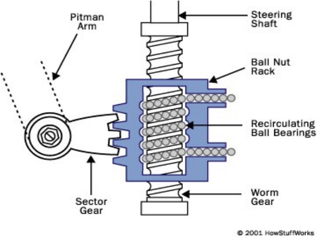
- Steering Wheel: Your interface with the system. Rotation translates to movement down the steering shaft.
- Steering Shaft: Connects the steering wheel to the steering gear (the heart of the system).
- Steering Gear (or Steering Box): This is the main assembly. It contains the worm shaft, ball nut, and sector shaft.
- Worm Shaft (or Steering Worm): A spiral-grooved shaft that rotates with the steering wheel.
- Ball Nut (or Ball Screw): A component surrounding the worm shaft that houses the recirculating ball bearings. This is the defining feature of this type of system!
- Recirculating Ball Bearings: These ball bearings roll between the worm shaft grooves and the ball nut, reducing friction and converting rotary motion into linear motion.
- Ball Guides (or Ball Returns): Channels that direct the ball bearings back to the start of the circuit, allowing continuous recirculation.
- Sector Shaft (or Pitman Shaft): A shaft with teeth (the sector) that meshes with the ball nut. Linear motion of the ball nut rotates the sector shaft.
- Pitman Arm: Connects the sector shaft to the steering linkage. It transmits the rotational motion of the sector shaft into linear motion.
- Steering Linkage: A system of rods and levers (e.g., tie rods, idler arm, center link) that connect the Pitman arm to the steering knuckles.
- Steering Knuckles: Pivoting points that allow the wheels to turn.
- Power Steering Pump (if equipped): Provides hydraulic assistance to reduce steering effort.
- Power Steering Hoses (if equipped): High-pressure and low-pressure lines connecting the pump, steering gear, and cooler (if present).
Understanding the Diagram's Symbols
Steering system diagrams use specific symbols to represent components and their connections. Here's a breakdown of common symbols:
- Solid Lines: Typically represent mechanical connections or hydraulic lines carrying high pressure. A thicker solid line might indicate a major structural component like the steering shaft.
- Dashed Lines: Often represent low-pressure hydraulic lines or signal paths (e.g., from a sensor to a control unit, if applicable in an electronically assisted system).
- Circles: May represent gears, pulleys, or bearings. In the case of a recirculating ball system, a circle with dots inside often represents the ball bearings.
- Rectangles: Commonly represent components like the power steering pump or a valve body within the steering gear.
- Arrows: Indicate the direction of movement or flow (e.g., fluid flow through a hose, rotational direction of a shaft).
- Spring Symbols: Represent springs within the system, which are used to apply preload or provide resistance.
- Labels: Each component should be clearly labeled with its name or a code for reference. Our diagram provides a key to decipher these labels.
- Color Coding (if present): Some diagrams use color to differentiate between hydraulic lines (e.g., red for high pressure, blue for low pressure) or to highlight specific subsystems.
Always refer to the diagram's legend or key to understand the specific symbols used.
How It Works: A Step-by-Step Explanation
Let's trace the path of motion through the system:
- Steering Wheel Rotation: When you turn the steering wheel, you rotate the steering shaft.
- Worm Shaft Engagement: The steering shaft turns the worm shaft within the steering gear.
- Ball Nut Movement: As the worm shaft rotates, the ball bearings in the ball nut roll along the grooves. This causes the ball nut to move linearly along the worm shaft. The recirculation of the balls is key to reducing friction.
- Sector Shaft Rotation: The linear motion of the ball nut engages with the sector shaft, causing it to rotate.
- Pitman Arm Activation: The rotating sector shaft moves the Pitman arm.
- Steering Linkage Translation: The Pitman arm pushes or pulls on the steering linkage, which transmits the motion to the steering knuckles.
- Wheel Turning: The steering knuckles pivot, causing the wheels to turn.
In a power steering system, the power steering pump provides hydraulic pressure that assists the movement of the ball nut. A valve within the steering gear regulates the amount of assistance based on the steering wheel input.
Real-World Use: Basic Troubleshooting Tips
Now, let's put this knowledge into practice. Here are some common issues and how the diagram can help you troubleshoot:
- Excessive Play in Steering: The diagram helps you trace the entire linkage from the steering wheel to the wheels. Check for wear or looseness in the Pitman arm connection, tie rod ends, idler arm, and any other points of articulation in the steering linkage. Internally, excessive play can be caused by wear of the ball bearings, worm shaft or ball nut inside the steering box.
- Steering Stiffness: If you have power steering, check the pump, hoses, and fluid level first. If those are OK, use the diagram to understand the valve system within the steering gear. A faulty valve could restrict fluid flow. If you *don't* have power steering, lubrication might be the problem. The diagram will show you the lubrication points (often grease fittings).
- Wandering Steering: This can be caused by loose steering linkage components (as above) or by improper alignment. The diagram helps you identify all the components that need to be checked for wear and proper adjustment.
- Power Steering Noise: Often indicates low fluid level, a failing pump, or air in the system. The diagram helps you trace the high and low pressure lines to identify potential leaks or restrictions.
Remember to always consult your vehicle's service manual for specific torque specifications and adjustment procedures.
Safety: Highlighting Risky Components
Steering systems, especially power steering systems, contain components under high pressure. Never disconnect hydraulic lines while the engine is running or the system is pressurized. Doing so can result in serious injury from high-pressure fluid injection. Furthermore, when disassembling the steering gear, be extremely careful. Internal components are often under spring pressure and can be ejected with force. Always wear safety glasses and follow the manufacturer's disassembly instructions precisely.
When working on the steering linkage, always use proper tools and torque specifications. Loose or improperly tightened components can lead to catastrophic steering failure.
We hope this article has given you a solid understanding of recirculating ball steering systems and how to interpret their diagrams. To help you even further, we have a detailed diagram available for download. Use it in conjunction with this guide to tackle your next steering system project with confidence!
Download the detailed recirculating ball steering system diagram here: [Insert Download Link Here]