Rectifier Regulator 5 Pin Voltage Regulator Wiring Diagram
Welcome, fellow gearheads! Today, we're diving deep into the fascinating world of the 5-Pin Rectifier Regulator wiring diagram. This component is crucial for maintaining stable voltage in your vehicle's electrical system, and understanding its wiring is essential for troubleshooting, repairs, or even custom builds. Whether you're battling dim headlights, a constantly dead battery, or embarking on an electrical modification project, grasping the ins and outs of this diagram will empower you to diagnose and solve problems with confidence.
Purpose: Why This Diagram Matters
The 5-Pin Rectifier Regulator diagram is your roadmap to understanding the electrical connections of a vital component in your vehicle's charging system. It matters because it allows you to:
- Diagnose charging system issues: Is your battery not charging correctly? The diagram helps pinpoint the source of the problem, whether it's a faulty regulator, a bad connection, or a wiring issue.
- Perform repairs: Need to replace a damaged connector or rewire a section of the charging system? The diagram provides the necessary information to do it correctly.
- Customize your electrical system: Adding aftermarket components like lights or accessories? Understanding the charging system and the regulator's role ensures you don't overload the system.
- Learn and understand: Perhaps you're just curious about how your vehicle's electrical system works. Studying the diagram provides valuable insight into the interplay of components.
Key Specs and Main Parts
Before we delve into the wiring diagram itself, let's familiarize ourselves with the key specs and main parts of a typical 5-Pin Rectifier Regulator:
Main Components:
- Rectifier: Converts AC (Alternating Current) from the alternator into DC (Direct Current), which is required to charge the battery and power your vehicle's electrical components. Think of it as a one-way valve for electricity.
- Regulator: Maintains a stable output voltage, typically around 13.5-14.5 volts DC. This protects sensitive electrical components from voltage spikes and ensures the battery is charged properly. Overvoltage is as bad as undervoltage!
- Heat Sink: Dissipates heat generated by the rectifier and regulator. These components produce a lot of heat, especially under heavy load.
- Connector: Provides the electrical connections for the various input and output wires. Typically a weatherproof connector to handle harsh environments.
Key Specs:
- Voltage Input: Varies depending on the vehicle, but generally accepts AC voltage from the alternator, typically ranging from 14-40V AC.
- Voltage Output: Regulated DC voltage, typically 13.5-14.5V DC. This is the voltage that charges the battery and powers the vehicle's electrical system.
- Current Capacity: Measured in Amperes (A). Indicates the maximum current the regulator can handle without damage. This is critical when adding electrical accessories.
- Operating Temperature: The range of temperatures in which the regulator can operate safely.
Symbols: Explaining Lines, Colors, and Icons
Understanding the symbols used in the wiring diagram is crucial for interpreting its information accurately.
- Lines: Represent wires or conductors. Thicker lines usually indicate wires carrying higher current. Dashed lines might indicate shielded wires or connections not always present in all models.
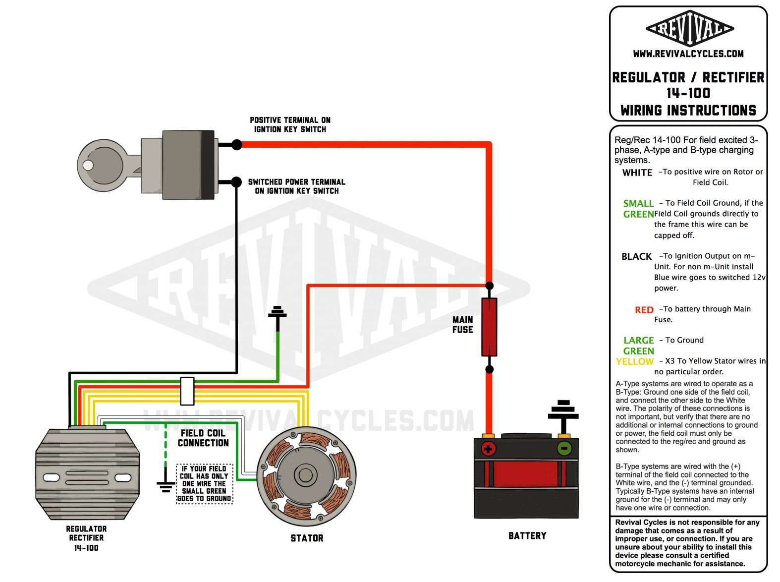
- Colors: Each color represents a specific wire function. Common colors and their typical functions include:
- Red: Positive (+) voltage, often directly connected to the battery.
- Black: Ground (-), connected to the vehicle's chassis or battery negative terminal.
- Yellow: AC input from the alternator (stator coils).
- Green: Often used for signals, such as voltage sensing or control signals.
- White/Blue: Can vary, but often used for other AC inputs from the alternator.
- Icons: Represent specific components. Here are a few common ones:
- Alternator: A symbol resembling a generator with a wavy line inside.
- Battery: Represented by a series of long and short parallel lines, indicating positive and negative terminals.
- Fuse: A zigzag line inside a rectangle.
- Ground: A series of horizontal lines decreasing in size, connected to a vertical line.
Remember that color coding can vary slightly depending on the vehicle manufacturer, so always refer to the specific diagram for your vehicle model.
How It Works
The 5-Pin Rectifier Regulator performs two crucial functions:
- Rectification: The alternator generates AC voltage, which is unsuitable for charging the battery or powering most of the vehicle's electrical components. The rectifier inside the regulator uses diodes to convert the AC voltage into DC voltage. Diodes are semiconductor devices that allow current to flow in only one direction, effectively "straightening" the alternating current.
- Regulation: The DC voltage from the rectifier can fluctuate significantly depending on engine speed and electrical load. The regulator maintains a stable output voltage by controlling the alternator's output. It does this by sensing the battery voltage and adjusting the field current supplied to the alternator. If the battery voltage is low, the regulator increases the field current, causing the alternator to produce more voltage. If the battery voltage is high, the regulator reduces the field current, decreasing the alternator's output. This feedback loop ensures a consistent and safe voltage for the entire electrical system.
The five pins typically perform the following functions:
- AC Input 1: AC voltage from one phase of the alternator stator.
- AC Input 2: AC voltage from another phase of the alternator stator.
- DC Output (+): Regulated DC voltage to charge the battery and power the vehicle's electrical system.
- Ground (-): Connected to the vehicle's chassis or battery negative terminal.
- Sense Wire (Optional): Some regulators have a sense wire that directly monitors the battery voltage. This provides more accurate voltage regulation, especially in vehicles with long wiring runs or heavy electrical loads. It's also possible this pin is used for a control signal from the ECU.
Real-World Use: Basic Troubleshooting Tips
Here are some basic troubleshooting tips using the wiring diagram:
- No Charging: If the battery isn't charging, check the DC output voltage of the regulator. Use a multimeter to measure the voltage between the DC output pin and ground. It should be around 13.5-14.5V DC with the engine running. If it's significantly lower or zero, the regulator may be faulty, or there may be a wiring issue.
- Overcharging: If the battery is constantly overcharging, check the DC output voltage of the regulator. If it's significantly higher than 14.5V DC, the regulator is likely faulty.
- Dim Headlights or Electrical Problems: These could indicate a faulty regulator or poor connections. Check the voltage at various points in the electrical system, starting at the battery and working your way towards the problem area. The wiring diagram can help you identify the correct test points.
- Burnt or Corroded Connectors: Inspect the regulator's connector for signs of damage or corrosion. Clean or replace the connector as needed. Remember to use dielectric grease to prevent future corrosion.
- Wiring Issues: Use the wiring diagram to trace the wires connected to the regulator. Look for damaged, frayed, or disconnected wires. Use a multimeter to check for continuity between different points in the circuit.
Safety: Highlight Risky Components
Working with electrical systems can be dangerous. Here are some safety precautions to take:
- Disconnect the Battery: Always disconnect the negative battery terminal before working on the electrical system. This prevents accidental short circuits and electrical shocks.
- Use Proper Tools: Use insulated tools designed for electrical work.
- Avoid Working in Wet Conditions: Water is a conductor of electricity. Avoid working on the electrical system in wet conditions.
- Be Careful with the Heat Sink: The heat sink can get very hot, especially after the engine has been running. Allow it to cool down before touching it.
- Capacitors can hold a charge even after the battery is disconnected. Be careful around the internals of the regulator.
The rectifier diodes within the regulator are especially sensitive to voltage spikes. Incorrect wiring or testing procedures can easily damage them. Be extra careful when measuring voltage or current in this area.
Remember, if you are not comfortable working with electrical systems, consult a qualified mechanic.
We hope this detailed explanation of the 5-Pin Rectifier Regulator wiring diagram has been helpful. We have the wiring diagram file available for download. Contact us through the form at the bottom of the page or speak to someone at the front desk and we will get that to you ASAP.