
Reese Trailer Brake Controller Wiring
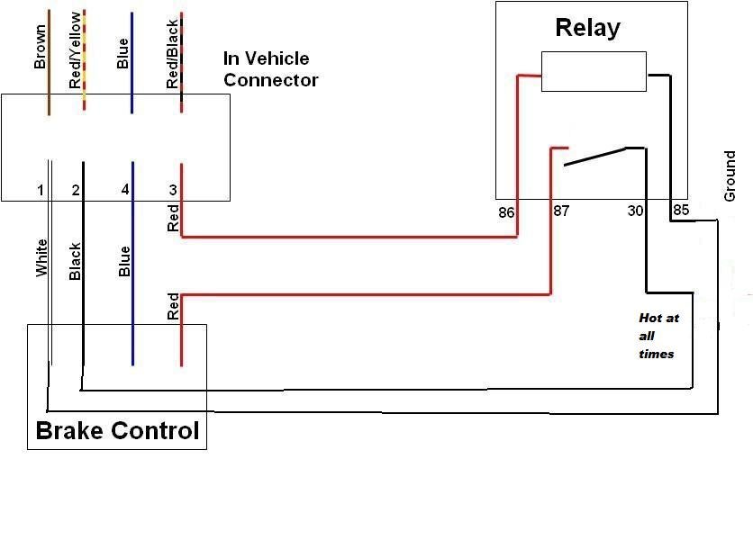
So, you're tackling a Reese trailer brake controller wiring job? Smart move. Understanding how these systems are wired is crucial for safe and reliable towing. Whether you're replacing a faulty controller, installing a new one, or just trying to diagnose a problem, knowing your way around the wiring diagram is essential. This article breaks down the intricacies of Reese trailer brake controller wiring, assuming you have a good handle on basic automotive electrical systems and are comfortable working with wiring tools. Think of me as your experienced colleague guiding you through the process.
Why This Diagram Matters
Let's be clear: deciphering a wiring diagram isn't just a theoretical exercise. It's about:
- Troubleshooting: When your trailer brakes aren't working correctly, a diagram is your roadmap to finding the fault.
- Installation: Installing a new controller correctly is impossible without understanding where each wire needs to go.
- Repair: Damaged wiring? A diagram shows you exactly which wire to replace and how to connect it properly.
- Safety: Improper wiring can lead to brake failure, electrical fires, or other dangerous situations.
- Learning: Understanding how a trailer brake controller is wired gives you a deeper understanding of vehicle electrical systems.
Ultimately, mastering these diagrams empowers you to maintain your towing setup safely and confidently. Let's dive into the details.
Key Specs and Main Parts
Before we examine the wiring, let's review the main components of a trailer brake controller system, specifically focusing on Reese controllers, and their typical wiring configurations. While specific wire colors and terminal assignments can vary slightly by model, the underlying principles remain the same.
- The Brake Controller: This is the brain of the system. It senses when you're braking and sends a signal to the trailer brakes to apply. Reese offers a range of controllers, from time-delayed to proportional.
- Wiring Harness: This connects the brake controller to the vehicle's wiring and the trailer connector. A pre-wired harness is highly recommended to prevent cutting and splicing.
- 7-Way Trailer Connector: This is the standard connector used to connect the trailer to the tow vehicle. It carries signals for brakes, lights, and other trailer functions.
- Vehicle's Brake Light Switch: The brake controller needs to know when you're pressing the brake pedal. It gets this information from the vehicle's brake light switch.
- Battery Power: The brake controller needs a direct connection to the vehicle's battery for power. This is crucial for proper operation.
- Ground Connection: A solid ground connection is essential for all electrical systems.
Typical Reese Controller Connections (Generic):
- Power Wire (Usually Black): Connected directly to the vehicle's battery positive terminal, often with a circuit breaker or fuse. This wire supplies the power for the entire braking system.
- Ground Wire (Usually White): Connected to a solid ground point on the vehicle's chassis. A clean, rust-free connection is critical.
- Brake Light Switch Wire (Often Blue or Red): Connected to the vehicle's brake light switch circuit. This wire senses when the brake pedal is pressed.
- Output Wire (Usually Blue): Sends the braking signal to the trailer's electric brakes via the 7-way connector.
Symbols: Lines, Colors, and Icons
Understanding wiring diagrams is like learning a new language. Here's a glossary of common symbols:
- Solid Lines: Represent wires. Thicker lines often indicate wires carrying higher current.
- Dashed Lines: Can indicate wires bundled together or wires that are optional, depending on the specific vehicle or model.
- Colors: Each wire has a color, usually abbreviated (e.g., BLK for black, WHT for white, BLU for blue, RED for red, GRN for green). These colors are standardized to help identify wires.
- Circles: Often represent connections or splices. A filled circle indicates a permanent connection.
- Rectangles: Can represent components like fuses, relays, or the brake controller itself.
- Zigzag Lines: Typically represent resistors or other components that impede the flow of current.
- Ground Symbol: Usually three horizontal lines getting progressively shorter, indicates a ground connection to the vehicle's chassis.
A typical Reese trailer brake controller wiring diagram will show these components and their connections clearly. You'll see lines representing the wires, labeled with their colors and gauge (wire thickness). The diagram will also show the connection points to the vehicle's wiring and the 7-way trailer connector.
How It Works
Here's a simplified explanation of how a Reese trailer brake controller works:
- Brake Pedal Activation: When you press the brake pedal, the vehicle's brake light switch closes, sending a signal to the brake controller.
- Controller Activation: The brake controller detects this signal and activates its internal circuitry.
- Proportional or Time-Delayed Braking: Depending on the type of controller, it will either apply the trailer brakes proportionally to the vehicle's braking force (proportional) or after a short delay (time-delayed). Proportional controllers use an internal sensor (often an accelerometer) to detect the rate of deceleration and adjust the trailer braking force accordingly.
- Signal to Trailer Brakes: The controller sends a variable voltage signal through the output wire (usually blue) to the trailer's electric brakes. The higher the voltage, the stronger the braking force.
- Trailer Brakes Activate: The electric brakes on the trailer receive the signal and apply braking force to the trailer's wheels.
The beauty of this system is that it synchronizes the trailer brakes with the vehicle's brakes, providing smooth and controlled stopping power. A properly functioning brake controller minimizes trailer sway and prevents premature wear on the vehicle's brakes.
Real-World Use: Basic Troubleshooting Tips
Here are a few common problems and how to troubleshoot them using your wiring diagram:
- No Trailer Brakes:
- Check the fuse or circuit breaker on the power wire.
- Verify the ground connection is clean and secure.
- Check the brake light switch wire connection.
- Use a multimeter to test for voltage at the output wire when the brake pedal is pressed.
- Weak Trailer Brakes:
- Check the brake controller's gain setting.
- Inspect the trailer brake wiring for corrosion or damage.
- Verify the trailer brakes are properly adjusted.
- Trailer Brakes Lock Up:
- Lower the brake controller's gain setting.
- Check for short circuits in the trailer brake wiring.
- Inspect the trailer brakes for mechanical problems.
Remember to always disconnect the battery before working on electrical components. Use a multimeter to test for voltage and continuity to diagnose problems. If you're unsure about anything, consult a qualified mechanic.
Safety: Highlight Risky Components
Working with automotive electrical systems can be dangerous. Here are some key safety precautions:
- Disconnect the Battery: Always disconnect the negative terminal of the battery before working on any electrical components. This prevents accidental shorts and electrical shocks.
- Fuse Protection: The power wire to the brake controller should always be protected by a fuse or circuit breaker. This prevents overcurrent situations that can lead to electrical fires.
- Proper Grounding: A poor ground connection can cause all sorts of problems, including voltage drops, erratic brake controller behavior, and even electrical fires. Make sure the ground connection is clean, secure, and connected to a solid point on the vehicle's chassis.
- Wire Gauge: Use the correct gauge wire for the application. Undersized wires can overheat and cause fires. Refer to the brake controller's installation instructions for the recommended wire gauge.
- Avoid Water: Keep electrical connections dry to prevent corrosion and short circuits. Use weatherproof connectors and sealants where necessary.
- High-Current Wires: The battery power wire is a high-current wire. Be extremely careful when working with this wire to avoid shorts or damage to the vehicle's electrical system.
Working with electricity can be dangerous. If you are not comfortable working on electrical systems, consult a qualified mechanic.
By understanding the wiring diagram and following these safety precautions, you can confidently install, troubleshoot, and repair your Reese trailer brake controller system. Safe towing is no accident; it's the result of knowledge, preparation, and careful execution.
We have a PDF file containing a detailed Reese trailer brake controller wiring diagram available for you to download. This diagram will be an invaluable resource as you work on your trailer braking system. Having it readily available will make your job much easier and more efficient.