
Remote Starter Solenoid Wiring Diagram
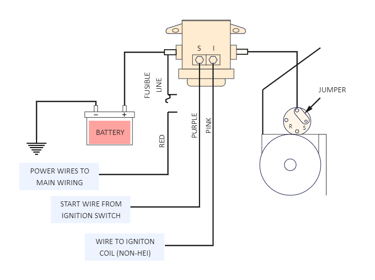
So, you're diving into the fascinating world of remote starter solenoid wiring! Understanding this circuit is crucial whether you're diagnosing starting problems, installing an aftermarket remote start system, or just expanding your automotive knowledge. This article will break down the typical wiring diagram, explaining the purpose, components, and troubleshooting techniques involved. We’re assuming you have some basic electrical experience; this isn't a “how to change a tire” guide, but rather a deep dive into a specific electrical system.
Why Understanding the Remote Starter Solenoid Wiring Matters
A solid grasp of the remote starter solenoid wiring diagram empowers you in several ways:
- Diagnostics: Pinpoint the source of starting issues, such as a dead battery, faulty solenoid, or wiring problem.
- Installation: Properly install aftermarket remote start systems, ensuring reliable operation and preventing damage to your vehicle's electrical system.
- Modification: Adapt or modify the starting system for custom projects or performance enhancements (with proper safety precautions, of course!).
- Knowledge: Become a more confident and capable car owner, able to troubleshoot and repair issues independently.
Key Specs and Main Parts
Let's dissect the primary components typically found in a remote starter solenoid wiring diagram:
- Battery (+12V): The heart of the electrical system, providing the power needed to start the engine.
- Ignition Switch: This switch, activated by the key, controls the flow of power to various circuits, including the starter solenoid. It has several positions: OFF, ACC (Accessory), ON, and START.
- Starter Solenoid: An electromagnetic switch that closes a high-current circuit to the starter motor when energized. The solenoid itself has two primary circuits:
- Control Circuit (Low Current): Energizes the solenoid's electromagnet, causing it to engage. This is typically triggered by the ignition switch or a remote start module.
- Power Circuit (High Current): Connects the battery directly to the starter motor when the solenoid is engaged.
- Starter Motor: A high-torque electric motor that cranks the engine, initiating the combustion process.
- Remote Start Module (Aftermarket): An electronic control unit that mimics the ignition switch's START position, activating the starter solenoid.
- Neutral Safety Switch (Automatic Transmissions): Prevents the engine from starting unless the transmission is in Park or Neutral. This is a critical safety feature. Manual transmission cars may have a clutch safety switch performing the same function.
- Fuses and Relays: Protective devices that prevent overcurrent and control high-current circuits with low-current signals, respectively.
- Wiring Harness: A bundle of wires that connects all the components together.
Symbols and Conventions in the Wiring Diagram
Understanding the symbols and conventions used in a wiring diagram is essential for accurate interpretation. Here are some common elements:
- Solid Lines: Represent wires. The thickness of the line may indicate the wire gauge (thicker lines = heavier gauge).
- Dashed Lines: May represent a shielded cable, a signal wire, or a ground connection. Context is key!
- Color Coding: Wires are typically color-coded to aid in identification and troubleshooting. Common colors include Red (power), Black (ground), Yellow (ignition), Blue (starter). Always verify with a reliable source, as color codes can vary by manufacturer.
- Symbols:
 Battery (a series of short and long parallel lines)
 Ground (a series of horizontal lines, decreasing in size)
 Fuse (a zig-zag line within a rectangle)
 Switch (a line that can open or close a circuit)
 Relay (a coil with a switch)
- Numbers and Labels: Wires are often labeled with numbers or letters to identify their function and destination. These labels are crucial for tracing circuits.
How It Works: The Starting Sequence
Let's walk through the starting sequence, tracing the electrical path:
- Key in START Position (or Remote Start Activation): Turning the ignition key to the START position (or activating the remote start system) sends a signal to the starter solenoid's control circuit. The remote start unit simulates this.
- Solenoid Activation: The control circuit energizes the solenoid's electromagnet. This electromagnet pulls a plunger, closing the high-current power circuit between the battery and the starter motor.
- Starter Motor Engagement: The high-current flow from the battery through the solenoid to the starter motor causes the starter motor to spin, engaging the engine's flywheel and cranking the engine.
- Engine Start: Once the engine starts, the ignition key is released (or the remote start module disengages), breaking the control circuit to the solenoid. The solenoid disengages, disconnecting the starter motor from the battery.
The Neutral Safety Switch (or clutch safety switch) is wired in series with the control circuit. This means the control circuit can only be completed (allowing the solenoid to activate) if the transmission is in Park or Neutral (or the clutch is depressed). This is a vital safety interlock.
Real-World Use: Basic Troubleshooting Tips
Here are some common starting problems and potential solutions, referencing the wiring diagram:
- Engine does not crank at all:
- Possible Cause: Dead battery, faulty solenoid, broken wire in the control circuit, faulty ignition switch, or a tripped neutral safety switch.
- Troubleshooting: Check battery voltage. Test the solenoid by applying 12V directly to the control terminal (be cautious!). Verify the ignition switch provides voltage to the solenoid control circuit when in the START position. Check the continuity of the neutral safety switch.
- Engine cranks but does not start: This is usually *not* a starter solenoid issue. Look into fuel and ignition problems.
- Clicking sound but engine does not crank:
- Possible Cause: Weak battery, corroded battery terminals, or a faulty solenoid. The solenoid may be engaging partially, but not providing enough current to the starter motor.
- Troubleshooting: Clean battery terminals. Load test the battery. Test the voltage drop across the solenoid's power circuit while attempting to start. A significant voltage drop indicates a bad connection or a failing solenoid.
- Remote start works, but key start doesn't (or vice versa): The problem likely lies in the wiring or module specific to the failing method. Check the remote start wiring for loose connections or blown fuses, and test the ignition switch and related wiring for the key start circuit.
Safety Precautions
Working with automotive electrical systems can be dangerous. Always prioritize safety:
- Disconnect the Battery: Before working on any electrical component, disconnect the negative (-) battery terminal. This prevents accidental shorts and electrical shocks.
- Work in a Well-Ventilated Area: Batteries can produce explosive hydrogen gas.
- Use Proper Tools: Use insulated tools designed for automotive electrical work.
- Be Careful with High-Current Circuits: The starter motor circuit carries a very high current. Shorting this circuit can cause severe damage and injury. Exercise extreme caution when working with these wires.
- The Starter Solenoid can get very hot during use. Exercise caution when handling.
- Never Bypass Safety Switches: The neutral safety switch is there for a reason. Bypassing it can lead to serious accidents.
- When in doubt, consult a professional. Electrical systems can be complex, and misdiagnosing or improperly repairing them can be dangerous and costly.
We've provided a basic solenoid wiring diagram file available for download. It should prove invaluable in understanding the system.