Remote Starter Switch Wiring Diagram
So, you're diving into remote starter installation or troubleshooting? Excellent! Understanding the remote starter switch wiring diagram is absolutely crucial. It's your roadmap, your guide, and frankly, your lifeline when dealing with these often-complex systems. Without it, you're essentially fumbling around in the dark, hoping you don't fry something expensive (or worse, yourself). This article will break down everything you need to know, from the basic components to real-world troubleshooting, all while keeping safety at the forefront.
Purpose of the Remote Starter Switch Wiring Diagram
Why bother with these diagrams? They're essential for several reasons:
- Installation: Installing a remote starter without the correct wiring diagram is asking for trouble. It shows you exactly where each wire needs to connect, ensuring proper functionality and preventing damage to your vehicle's electrical system.
- Troubleshooting: Having issues with an existing remote starter? The wiring diagram allows you to trace circuits, identify faulty connections, and pinpoint the source of the problem. Trying to troubleshoot without it is like trying to find a needle in a haystack.
- Understanding: Even if you're not actively working on a remote starter, studying the wiring diagram can greatly improve your understanding of automotive electrical systems in general. It allows you to visualize how different components interact and how signals are routed.
- Repair: Accidents happen. Wires get cut, connectors break. The diagram lets you safely and accurately repair or replace damaged components.
Key Specs and Main Parts
Before we delve into the intricacies of the wiring diagram, let's cover the key components you'll typically find in a remote starter system:
- Remote Starter Module: This is the brain of the operation. It receives the signal from the remote, interprets it, and activates the necessary circuits to start the vehicle. Think of it as a mini-computer dedicated to starting your car.
- Remote Transmitter (Key Fob): The device you use to send the start command to the remote starter module.
- Wiring Harness: A bundle of wires that connect the remote starter module to various points in the vehicle's electrical system. These wires carry power, ground, and signals to control different functions.
- Relays: Electromagnetic switches that allow the remote starter to control high-current circuits, such as the starter motor. A small current activates the relay, which then closes a circuit to handle a larger current.
- Hood Pin Switch: A safety switch that prevents the remote starter from operating if the hood is open. This is a crucial safety feature to prevent accidental starting while someone is working under the hood.
- Brake Pedal Switch: Another safety switch that disables the remote starter if the brake pedal is pressed. This helps prevent the vehicle from moving unexpectedly during remote start.
- Tachometer Wire (or Signal): Used to monitor engine RPM. The remote starter uses this signal to determine if the engine has successfully started.
- Immobilizer Bypass Module (if needed): Many modern vehicles have an immobilizer system that prevents the engine from starting without the correct key present. This module bypasses the immobilizer during remote start.
- Ground Wire: Provides a return path for electrical current and is crucial for proper circuit operation. A good, clean ground connection is essential.
- Power Wire: Supplies power from the vehicle's battery to the remote starter module. Typically, this wire is fused for safety.
Symbols – Deciphering the Diagram
Understanding the symbols used in a remote starter wiring diagram is essential for interpreting it correctly. Here's a breakdown of common symbols:
- Solid Lines: Represent wires. Thicker lines often indicate wires carrying higher current.
- Dashed Lines: May represent optional connections or wires that are only present in certain vehicle models.
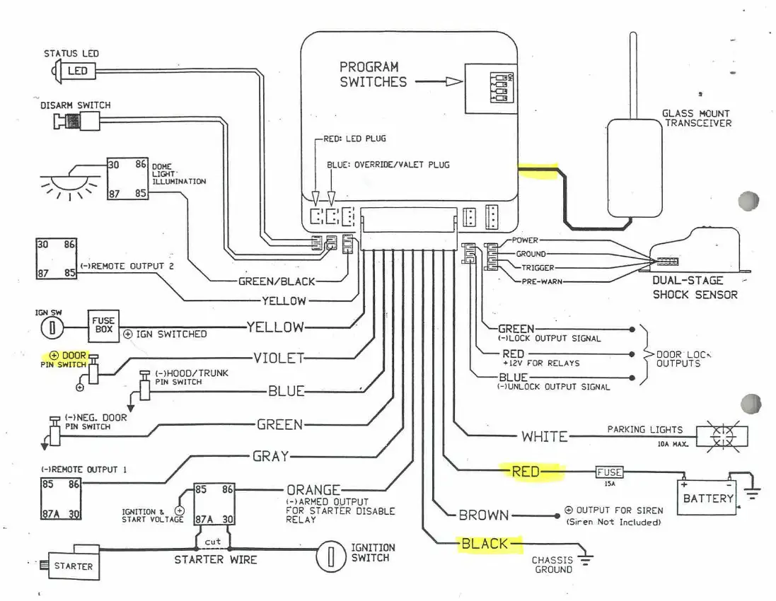
- Colors: Wires are typically color-coded. The diagram will usually include a legend indicating what each color represents (e.g., Red = +12V, Black = Ground, Blue = Starter Wire). Adhering to the color codes is extremely important.
- Circles with a Cross: Represent wire splices or connection points.
- Rectangles: Often represent components like relays, switches, or the remote starter module itself.
- Ground Symbol (Typically three descending horizontal lines): Indicates a connection to the vehicle's chassis, providing a ground path.
- Battery Symbol: Represents the vehicle's battery.
- Fuse Symbol: Represents a fuse, a safety device that protects the circuit from overcurrent.
Important Color Codes (These are generalized; always consult the specific diagram for your vehicle and remote starter):
- Red: +12V (Constant Power)
- Orange: +12V (Accessory Power)
- Yellow: +12V (Ignition Power)
- Black: Ground
- Purple: Starter Wire
- Blue: Typically used for remote start activation or status output.
How It Works: A Step-by-Step Overview
Here's a simplified explanation of how a remote starter system works, referencing the wiring diagram:
- Remote Activation: You press the start button on the remote transmitter. This sends a radio frequency (RF) signal to the remote starter module.
- Module Receives Signal: The remote starter module receives the RF signal and verifies its validity.
- Safety Checks: The module checks the safety switches (hood pin, brake pedal) to ensure it's safe to start the engine.
- Immobilizer Bypass (if necessary): The module activates the immobilizer bypass module to temporarily disable the vehicle's immobilizer system.
- Ignition and Accessory Activation: The module activates the ignition and accessory circuits, providing power to the necessary components for starting the engine. This is done through relays controlled by the module.
- Starter Motor Engagement: The module activates the starter relay, which sends power to the starter motor, cranking the engine.
- Engine Running Confirmation: The module monitors the tachometer wire (or other RPM signal) to confirm that the engine has started successfully.
- Sustained Operation: Once the engine is running, the module continues to provide power to the ignition and accessory circuits, keeping the engine running for a pre-set amount of time or until the remote start is deactivated.
Real-World Use – Basic Troubleshooting Tips
Here are some common problems and how a wiring diagram can help you diagnose them:
- Remote Starter Not Working at All:
- Check the main power and ground connections to the remote starter module. Use the wiring diagram to locate these wires and ensure they have a solid connection. Use a multimeter to verify voltage and continuity.
- Check the fuse on the power wire. A blown fuse is a common cause of failure.
- Verify the remote's battery.
- Engine Cranks But Doesn't Start:
- Check the immobilizer bypass module (if applicable). Ensure it's properly connected and functioning.
- Verify the connection to the tachometer wire. The module needs to see an RPM signal to know the engine has started.
- Remote Starter Starts the Engine, But It Immediately Shuts Off:
- This can also be related to the tachometer wire or the immobilizer bypass. Double-check these connections.
- Could also be a low voltage issue. Check the voltage at the battery during cranking.
- Remote Starter Works Intermittently:
- Look for loose connections or corroded terminals. Use the wiring diagram to trace the circuits and inspect each connection point.
- Consider a failing relay. Relays can sometimes work intermittently before failing completely.
Always refer to the wiring diagram specific to your vehicle and remote starter model for accurate troubleshooting. Generic diagrams can provide a general understanding, but the specific wiring configurations can vary significantly.
Safety – Highlighting Risky Components
Working with automotive electrical systems can be dangerous if you're not careful. Here are some important safety precautions:
- Disconnect the Battery: Always disconnect the negative terminal of the vehicle's battery before working on the electrical system. This prevents accidental shorts and potential electrical shocks.
- Work in a Well-Ventilated Area: Working on a car often involves fumes from gasoline, oil, or other chemicals. Ensure you have adequate ventilation to avoid inhaling harmful vapors.
- Use Proper Tools: Use insulated tools designed for automotive electrical work. This will help prevent accidental shorts and protect you from electric shock.
- Avoid Working on Live Circuits: If you absolutely must work on a live circuit, use extreme caution and wear appropriate personal protective equipment (PPE), such as insulated gloves and eye protection.
- Be Aware of Airbags: Modern vehicles have airbags that can deploy unexpectedly if triggered by electrical signals. Consult the vehicle's service manual for instructions on disabling the airbag system before working on any electrical components near the airbags.
- Identify High-Current Wires: The thick red wire connected directly to the battery carries a large amount of current. Avoid accidentally shorting this wire to ground.
- Double-Check Your Work: Before reconnecting the battery, carefully review your work and ensure that all connections are secure and properly insulated.
- When in doubt, seek professional help. If you're uncomfortable working on automotive electrical systems, it's best to consult a qualified mechanic or remote starter installer.
Remember, safety is paramount. Taking a few extra minutes to prepare and follow safety precautions can prevent serious injuries and costly damage to your vehicle.
We have a comprehensive collection of remote starter switch wiring diagrams available. Click the download button below to access the diagram that best suits your specific remote starter and vehicle model. Always double-check the diagram's part number and compatibility before use.