Riding Mower 7 Prong Ignition Switch Wiring Diagram
If you're an experienced DIYer who enjoys tinkering with small engines, understanding the wiring diagram of your riding mower's 7-prong ignition switch is crucial. This knowledge empowers you to perform repairs, diagnose electrical issues, or even modify your mower with confidence. Forget costly shop visits; armed with this knowledge, you can become your own lawnmower mechanic!
Why Bother Understanding the Ignition Switch Wiring Diagram?
The ignition switch is the heart of your riding mower's electrical system. It's not just about starting the engine; it controls various circuits responsible for starting, running, charging the battery, and engaging safety features. A faulty ignition switch or wiring problem can manifest in a myriad of frustrating symptoms, including:
- The mower won't start.
- The engine cranks but doesn't fire.
- The mower shuts off intermittently.
- The charging system malfunctions.
- Safety interlocks (like the seat switch) don't function correctly.
Having a solid understanding of the ignition switch wiring diagram allows you to diagnose these problems systematically. It gives you a roadmap to follow, enabling you to pinpoint the source of the issue, whether it's a broken wire, a corroded connection, or a faulty switch. Furthermore, if you are planning on adding some accessories like lights or USB charger, knowing how the starting system of the mower works will help prevent you from damaging the electric systems.
Key Specs and Main Parts of a 7-Prong Ignition Switch
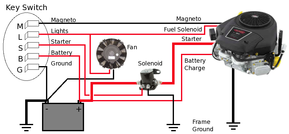
The 7-prong ignition switch is a common type found in many riding mowers. Each prong, or terminal, corresponds to a specific circuit. Understanding their functions is key to deciphering the wiring diagram.
Here's a breakdown of the typical terminals and their functions. Keep in mind that the exact color coding and terminal designations can vary slightly between mower manufacturers, so always refer to your specific mower's wiring diagram.
- B (Battery): This terminal connects directly to the positive (+) terminal of the battery. It provides the main power source for the electrical system. Typically, this wire is a heavy-gauge red wire.
- S (Start): This terminal activates the starter solenoid. When the key is turned to the "start" position, this terminal sends power to the solenoid, which engages the starter motor to crank the engine. The wire connected here is often yellow or purple.
- I (Ignition): This terminal provides power to the ignition coil or module when the key is in the "run" position. This circuit enables the engine to fire. Expect a blue or black wire here.
- L (Lights): Powers the lights. This is usually activated in the "run" position or a dedicated "lights" position on the switch. This wire is frequently black or blue.
- M (Magneto/Ground): This terminal grounds the magneto ignition system to stop the engine. When the key is turned to the "off" position, this terminal connects the magneto to ground, preventing it from producing a spark and shutting down the engine. The wire on this terminal is often black or green. Important: Never apply voltage to this terminal, as it could damage the ignition module.
- A (Accessory): Provides power to accessory components, such as electric PTO clutches or hour meters. It's typically only active in the "run" position. This wire may be orange or gray.
- R (Rectifier/Regulator): This terminal connects to the rectifier/regulator, which controls the battery charging system. This terminal ensures that the battery receives the correct voltage for charging.
In addition to the terminals, the ignition switch itself consists of a rotating cylinder that makes electrical contact between these terminals in different key positions (Off, Run, Start, Lights).
Decoding the Symbols in the Wiring Diagram
Wiring diagrams use a standardized set of symbols to represent different components and connections. Understanding these symbols is essential for interpreting the diagram.
- Solid Lines: Represent wires. The thickness of the line sometimes indicates the gauge (thickness) of the wire.
- Dashed Lines: May represent shielded wires or wires that are part of a harness.
- Colors: Each wire is typically identified by its color. Common colors include red, black, blue, green, yellow, and white. Always double-check the diagram for the specific color coding used for your mower model.
- Circles with Numbers: Represent wiring connectors or terminals. The numbers indicate the specific terminal or pin number.
- Rectangles: Usually represent components like the ignition switch, relays, or fuses.
- Ground Symbol (usually three horizontal lines decreasing in length): Indicates a connection to the chassis ground (the metal frame of the mower).
- Battery Symbol (alternating long and short lines): Represents the battery.
- Switch Symbol (a line connected to a hinged arm): Represents a switch. The position of the arm indicates whether the switch is open or closed.
How It Works: A Simplified Explanation
Let's trace the flow of electricity through the ignition switch in different key positions:
- Off: The "M" (Magneto/Ground) terminal is connected to ground, preventing the engine from starting. No other circuits are energized.
- Run: The "B" (Battery) terminal is connected to the "I" (Ignition) terminal, providing power to the ignition coil. The "A" (Accessory) terminal might also be energized, depending on the mower's design. The "R" (Rectifier/Regulator) terminal will be connected to the charging circuit. The "L" terminal can also be connected if the mower is running lights.
- Start: In addition to the "Run" connections, the "B" (Battery) terminal is also connected to the "S" (Start) terminal, sending power to the starter solenoid.
The safety interlocks, such as the seat switch and blade engagement switch, are typically wired in series with the ignition circuit. This means that all safety switches must be closed (indicating safe conditions) for the engine to start. If any of these switches are open, the circuit is broken, and the engine will not crank or fire.
Real-World Use: Basic Troubleshooting Tips
Here are a few common troubleshooting scenarios and how to use the wiring diagram to diagnose them:
- Mower won't start at all:
- Check the battery voltage.
- Inspect the battery connections for corrosion.
- Verify that the safety interlocks are engaged (seat switch, blade switch).
- Use a multimeter to check for voltage at the "B" (Battery) terminal of the ignition switch. If there's no voltage here, the problem is likely in the battery or the wiring between the battery and the switch.
- Turn the key to the "Start" position and check for voltage at the "S" (Start) terminal. If there's no voltage here, the ignition switch is likely faulty.
- Mower cranks but doesn't fire:
- Check for spark at the spark plug.
- Verify that the "I" (Ignition) terminal is receiving voltage in the "Run" position. If not, the ignition switch or the wiring to the ignition coil may be the problem.
- Mower shuts off intermittently:
- This could be caused by a loose connection, a faulty safety interlock, or a failing ignition switch. Carefully inspect all wiring connections and safety switches.
Safety First!
Working with electrical systems can be dangerous. Always disconnect the battery before working on the wiring. Be especially careful when working around the starter solenoid and the ignition coil. These components can deliver high voltage and amperage, which can cause serious injury. Also, avoid using jumper wires to bypass safety switches unless you understand the circuit and the potential risks. Doing so could create a dangerous situation or damage the electrical system. When working with electrical components, use properly insulated tools. Remember the "M" (Magneto/Ground) terminal can damage the ignition module if voltage is applied.
We have a detailed 7-prong ignition switch wiring diagram available for download. It includes color-coded wiring details and component locations. With this diagram and the knowledge you've gained here, you'll be well-equipped to tackle most electrical issues on your riding mower. Now go forth and conquer that lawn!