Schematic 2006 Chevy Silverado Brake Line Diagram
Let's dive into the brake system of a 2006 Chevy Silverado. Having a solid understanding of the brake line diagram is crucial whether you're tackling a brake job yourself, trying to diagnose a leak, or just expanding your automotive knowledge. This article will serve as a guide to deciphering the schematic and applying that knowledge to real-world scenarios. We even have a PDF file of the 2006 Chevy Silverado brake line diagram available for you to download, linked at the end of the article.
Purpose of the 2006 Chevy Silverado Brake Line Diagram
The brake line diagram is your roadmap to the entire braking system. It visually represents all the brake lines, components, and their interconnections. It's invaluable for:
- Repairs: Locating leaks, identifying damaged lines, and understanding how to properly replace them.
- Diagnostics: Tracing pressure drops or imbalances within the system.
- Modification: Planning upgrades or modifications, such as installing stainless steel brake lines or upgrading calipers.
- Learning: Gaining a deeper understanding of how the braking system functions.
Key Specs and Main Parts
The 2006 Chevy Silverado utilizes a hydraulic braking system. Here's a breakdown of the key components you'll find in the diagram:
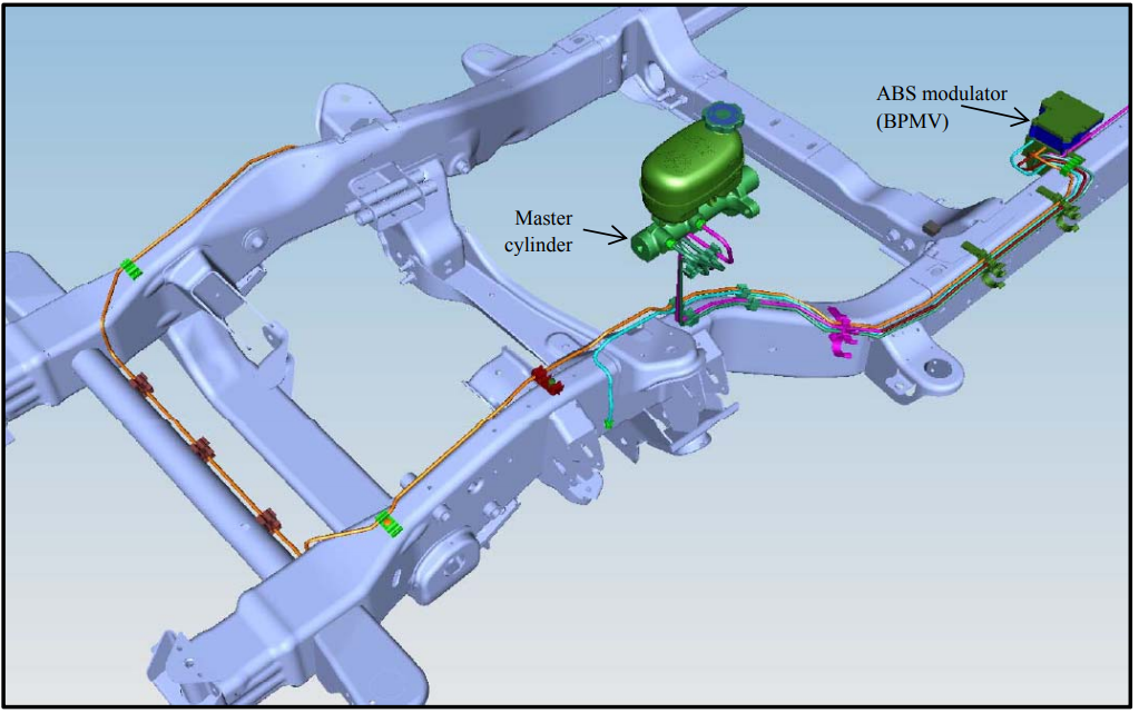
- Master Cylinder: The heart of the system, it generates hydraulic pressure when you depress the brake pedal. It typically has two separate reservoirs, one for the front brakes and one for the rear.
- Brake Lines (Steel/Hydraulic Hoses): These lines carry brake fluid from the master cylinder to the wheel cylinders or calipers. Steel lines are used for long runs along the frame, while flexible hydraulic hoses connect to the wheels to accommodate suspension movement.
- Proportioning Valve: This valve regulates the pressure applied to the rear brakes, preventing them from locking up before the front brakes during hard stops.
- ABS (Anti-lock Braking System) Module: If equipped, this module electronically controls brake pressure to individual wheels to prevent wheel lockup during braking. The diagram will show the integration of the ABS module into the brake lines. The ABS module contains solenoids and a pump to adjust pressure.
- Wheel Cylinders (Rear Drum Brakes): Convert hydraulic pressure into mechanical force to push the brake shoes against the brake drums.
- Calipers (Front/Rear Disc Brakes): Convert hydraulic pressure into mechanical force to squeeze the brake pads against the brake rotors. They contain pistons that push the brake pads.
- Brake Rotors/Drums: The rotating surfaces against which the brake pads or shoes are applied to create friction and slow the vehicle.
- Brake Pads/Shoes: The friction material that contacts the rotors or drums to slow the vehicle.
The brake system also incorporates various fittings, connectors, and bleeder screws that are represented in the schematic. The diagram will also typically show the location of ground points associated with the ABS system.
Symbols – Interpreting the Brake Line Diagram
Understanding the symbols used in the diagram is essential for proper interpretation. Here are some common symbols you'll encounter:
- Solid Lines: Typically represent steel brake lines.
- Dashed Lines: Often represent flexible hydraulic hoses.
- Circles: Usually indicate fittings or connectors.
- Rectangles: May represent valves, such as the proportioning valve or components within the ABS module.
- T-Junctions: Show where a brake line splits into two.
- Colors: Some diagrams use color-coding to differentiate between front and rear brake circuits or different line sizes. If color is used, the legend will explain the color codes.
- Arrowheads: Can indicate the direction of brake fluid flow.
It's important to refer to the specific legend provided with the 2006 Chevy Silverado brake line diagram you're using, as symbols can vary slightly. Also, note the line thickness in the diagram, sometimes line thickness represents the diameter or pressure rating of the line.
How It Works – The Braking Process
Let's break down the braking process, as represented in the diagram:
- When you press the brake pedal, the master cylinder generates hydraulic pressure.
- This pressure travels through the brake lines to the wheels.
- For vehicles without ABS, the pressure is distributed directly to the front calipers and, after being regulated by the proportioning valve, to the rear wheel cylinders or calipers.
- For vehicles *with* ABS, the pressure first goes to the ABS module. The ABS module monitors wheel speed and can independently regulate the pressure to each wheel to prevent lockup.
- At the wheels, the pressure activates the calipers or wheel cylinders, applying the brake pads or shoes to the rotors or drums, slowing the vehicle.
- When you release the brake pedal, the pressure is released, and the brake pads or shoes retract.
The diagram illustrates this entire process, showing the path of the brake fluid and the interaction of the various components. Note the routing of brake lines. Typically, manufacturers keep the lines away from heat sources and moving suspension parts.
Real-World Use – Basic Troubleshooting Tips
Here are some practical troubleshooting tips using the brake line diagram:
- Brake Fluid Leak: If you notice a leak, use the diagram to trace the brake lines from the master cylinder to the wheels. Look for wet spots or corrosion around fittings and connections. The diagram will help you pinpoint the exact location of the leak and determine which component needs to be replaced.
- Soft Brake Pedal: A soft or spongy brake pedal can indicate air in the brake lines. The diagram can help you identify the bleeder screws on each caliper or wheel cylinder. Use the proper bleeding procedure (starting with the wheel furthest from the master cylinder) to remove air from the system.
- Uneven Braking: If the vehicle pulls to one side during braking, it could indicate a problem with one of the brake circuits. The diagram can help you isolate the issue to a specific wheel or circuit. Check for stuck calipers, worn brake pads, or a malfunctioning proportioning valve.
- ABS Light On: If the ABS light is illuminated, the diagram can help you understand the layout of the ABS system and identify the location of the ABS module, wheel speed sensors, and related wiring. *Diagnostic trouble codes (DTCs)* will point you to the malfunctioning area, and the diagram can help you understand where to start your diagnosis.
Safety – Important Considerations
Working on brake systems involves inherent risks. Here are some crucial safety precautions:
- Brake Fluid: Brake fluid is corrosive and can damage paint and other surfaces. Wear eye protection and gloves when handling brake fluid. Clean up any spills immediately.
- Contamination: Keep brake fluid clean and free of contaminants. Never use old or used brake fluid. Even a small amount of contamination can compromise the braking system's performance.
- Pressure: The brake system operates under high pressure. Always relieve the pressure before disconnecting any brake lines.
- Proper Tools: Use the correct tools for the job. Avoid using pliers or wrenches that can damage brake lines or fittings. Use flare nut wrenches to avoid rounding off the fittings.
- Torque Specifications: Always tighten brake line fittings to the manufacturer's specified torque. Over-tightening can damage the fittings, while under-tightening can cause leaks. Consult a service manual for the correct torque values.
- Thorough Inspection: After completing any brake work, thoroughly inspect the entire system for leaks or other problems. Test the brakes carefully before driving the vehicle.
- ABS System Precautions: When working on vehicles with ABS, follow the manufacturer's specific instructions for bleeding the brakes and resetting the ABS module. Some ABS systems require special tools or procedures. Improper bleeding can damage the ABS system.
Crucially, remember that the brake system is a critical safety component. If you're not comfortable working on brakes, it's best to seek the assistance of a qualified mechanic. Don't be afraid to admit when a job is beyond your current skill level.
Understanding the brake line diagram is a powerful tool for diagnosing and repairing brake system issues on your 2006 Chevy Silverado. With careful study and attention to detail, you can confidently tackle many common brake-related problems.
We have the complete 2006 Chevy Silverado brake line diagram available for download. Click here to download: Download 2006 Chevy Silverado Brake Line Diagram