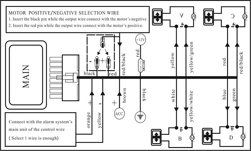
Schematic 5 Pin Power Window Switch Wiring Diagram
The 5-pin power window switch wiring diagram is a critical piece of information for anyone working on automotive electrical systems. Whether you're diagnosing a faulty window, adding aftermarket accessories, or simply trying to understand how your car's electronics function, mastering this diagram is invaluable. We're not talking about just poking around; we're talking about understanding the flow of electricity and how each component interacts. This knowledge empowers you to confidently tackle repairs, perform modifications, and gain a deeper appreciation for automotive engineering. We have a detailed diagram available for you to download, which we'll mention again later.
Purpose of the 5-Pin Power Window Switch Wiring Diagram
Why bother learning about this diagram? Several key reasons stand out:
- Troubleshooting: A non-functioning power window is a common problem. The wiring diagram allows you to systematically trace the electrical path, identifying breaks, shorts, or faulty components like the switch or motor.
- Repairing: Once the problem is identified, the diagram guides you in making the necessary repairs, whether it's replacing a wire, cleaning a connection, or swapping out a component.
- Modification: Adding aftermarket components, such as remote window control or automatic up/down modules, requires understanding the existing wiring. The diagram provides the foundation for safely integrating these modifications.
- Understanding: Even if you don't plan on making repairs yourself, understanding the electrical system empowers you to communicate more effectively with mechanics and make informed decisions about your vehicle's maintenance.
- Learning: Studying the diagram deepens your understanding of basic electrical principles and how they are applied in automotive applications. It's a stepping stone to tackling more complex automotive electrical projects.
Key Specs and Main Parts
Let's break down the key specifications and parts involved in a typical 5-pin power window system. The core components are:
- Power Window Switch: This is the central control point. It redirects power to the window motor in either the up or down direction. It's usually a DPDT (Double Pole, Double Throw) switch with a center-off position.
- Power Window Motor: This is a DC motor that drives the window regulator mechanism. Its polarity determines the direction of rotation (up or down).
- Window Regulator: This is the mechanical linkage that translates the motor's rotation into the linear motion of the window glass.
- Fuse: A crucial safety device that protects the circuit from overcurrent. It's typically located in the fuse box and is rated for a specific amperage (e.g., 20A).
- Wiring Harness: This is the collection of wires that connect all the components. The wires are typically color-coded for easy identification.
- Ground Connection: Provides a return path for the electrical current. A good ground connection is essential for proper operation.
The 5-pin configuration of the switch is usually broken down like this (though it may vary slightly by manufacturer, so always consult the specific diagram for your vehicle):
- Pin 1: Power Input (usually +12V from the fuse).
- Pin 2: Ground.
- Pin 3: Motor Up.
- Pin 4: Motor Down.
- Pin 5: Illumination (sometimes, often linked to dashboard lighting).
Symbols in the Wiring Diagram
Understanding the symbols used in the wiring diagram is essential for interpreting the information. Here's a breakdown of the most common symbols:
- Lines: Solid lines represent wires, indicating the path of electrical current. Dashed lines may indicate shielding or grounding. The thickness of the line doesn't typically represent the wire gauge in most basic automotive schematics.
- Circles: Often represent connection points or terminals.
- Rectangles: Typically represent components like switches, relays, or control modules.
- Zigzag Line: Represents a resistor.
- M with a Circle: Represents the electric motor.
- Ground Symbol (usually a series of horizontal lines decreasing in length): Indicates a connection to the vehicle's chassis ground. This is critically important for completing the circuit.
- Fuse Symbol (often a squiggly line enclosed in a rectangle): Indicates a fuse. The amperage rating is usually indicated next to the symbol.
Color Coding: Wires are typically color-coded to aid in identification. Common colors include red (power), black (ground), blue, green, yellow, and white. The specific color code can vary between manufacturers and models, so always refer to the specific diagram for your vehicle. Standard conventions usually show Red/Red with stripe as a power wire, and Black/Black with stripe as ground, and other colors signal wires.
How It Works: The Electrical Flow
The power window system operates by directing power to the window motor based on the position of the switch. Let's trace the electrical flow:
- Power Source: Power is supplied from the vehicle's battery, typically through a fuse to protect the circuit from overcurrent.
- Switch Input: The power (usually +12V) enters the power window switch at Pin 1.
- Neutral Position: When the switch is in the neutral (center) position, no power is directed to the motor.
- Up Position: When the switch is moved to the "up" position, it connects Pin 1 to Pin 3 (Motor Up). This sends power to the motor, causing it to rotate in one direction, raising the window. The ground connection at the motor completes the circuit.
- Down Position: When the switch is moved to the "down" position, it connects Pin 1 to Pin 4 (Motor Down). This sends power to the motor with the polarity reversed, causing it to rotate in the opposite direction, lowering the window.
- Ground: Pin 2 of the switch provides a ground connection, which is essential for completing the circuit.
The beauty of the 5-pin switch is its ability to reverse the polarity of the voltage applied to the motor, enabling bidirectional control. This is the fundamental principle behind power window operation.
Real-World Use: Basic Troubleshooting Tips
Here are some basic troubleshooting tips for a non-functioning power window, using the wiring diagram as a guide:
- Check the Fuse: This is the first and easiest step. Use a multimeter to test for continuity across the fuse. If the fuse is blown, replace it with one of the same amperage rating.
- Test the Switch: Use a multimeter to test the switch for continuity. With the switch in the neutral position, there should be no continuity between the power input (Pin 1) and either the Motor Up (Pin 3) or Motor Down (Pin 4) pins. In the up position, there should be continuity between Pin 1 and Pin 3. In the down position, there should be continuity between Pin 1 and Pin 4.
- Check the Motor: Disconnect the motor connector and use a multimeter to test for resistance across the motor terminals. An open circuit indicates a faulty motor. You can also try applying +12V directly to the motor terminals to see if it spins (be mindful of polarity).
- Check the Wiring: Visually inspect the wiring harness for any signs of damage, such as cuts, frayed wires, or corroded connectors. Use a multimeter to test for continuity between the switch and the motor.
- Check the Ground Connection: Ensure that the ground connection is clean and secure. A loose or corroded ground connection can cause a variety of electrical problems.
Example Scenario: If the window only goes down but not up, the issue likely lies in the switch's "up" contact, the wiring between the switch and the motor for the "up" direction, or the motor itself. The wiring diagram allows you to isolate the problem area and focus your troubleshooting efforts.
Safety Considerations
Working with automotive electrical systems can be dangerous if proper precautions are not taken. Here are some safety considerations:
- Disconnect the Battery: Always disconnect the negative terminal of the battery before working on any electrical components. This prevents accidental shorts and potential electrical shocks.
- Use Proper Tools: Use insulated tools designed for electrical work.
- Avoid Water: Never work on electrical systems in wet conditions.
- Be Mindful of Airbags: Be extremely careful when working near airbag modules. Accidental activation can cause serious injury. If you are unsure of what you are doing, consult a professional.
- Fuses are Critical: Never replace a fuse with one of a higher amperage rating. This can overload the circuit and cause a fire.
The power window motor, while seemingly simple, can draw a significant amount of current. Accidental short circuits can generate heat quickly. Always use a fuse to protect the circuit.
Understanding and utilizing the 5-pin power window switch wiring diagram is an empowering skill for any car enthusiast. By following the principles and safety guidelines outlined above, you can confidently tackle repairs, perform modifications, and deepen your understanding of automotive electrical systems. And remember, we have a downloadable file of the wiring diagram available to assist you with your projects. We hope you find it helpful!