Schematic 5 Prong Ignition Switch Wiring Diagram
Understanding the 5-prong ignition switch wiring diagram is crucial for any DIY mechanic tackling electrical issues, performing modifications, or even just learning about automotive systems. This diagram acts as a roadmap, allowing you to trace circuits, diagnose problems, and perform safe and effective repairs. Let's delve into the details.
Purpose and Importance
Why bother with a 5-prong ignition switch diagram? The answer is simple: it unlocks the mysteries of your car's starting and running systems. Imagine trying to fix a leaky faucet without knowing how the pipes are connected – that's what working on your ignition system without a diagram is like. This document is indispensable for:
- Troubleshooting Starting Issues: Is your car failing to start? The diagram helps you pinpoint whether the problem lies in the ignition switch itself, the starter motor, the solenoid, or related wiring.
- Performing Aftermarket Installations: Adding accessories like remote starters or security systems often requires tapping into the ignition circuit. A diagram ensures you do it correctly and avoid frying your electrical system.
- Understanding Automotive Electrical Systems: Even if you're not actively working on your car, studying the diagram provides valuable insights into how the ignition system interacts with other electrical components.
- Preventing Electrical Fires: Incorrect wiring can lead to shorts and potentially dangerous fires. Proper diagram usage minimizes this risk.
Key Specs and Main Parts of a 5-Prong Ignition Switch
Before diving into the wiring itself, let's identify the key components and their functions:
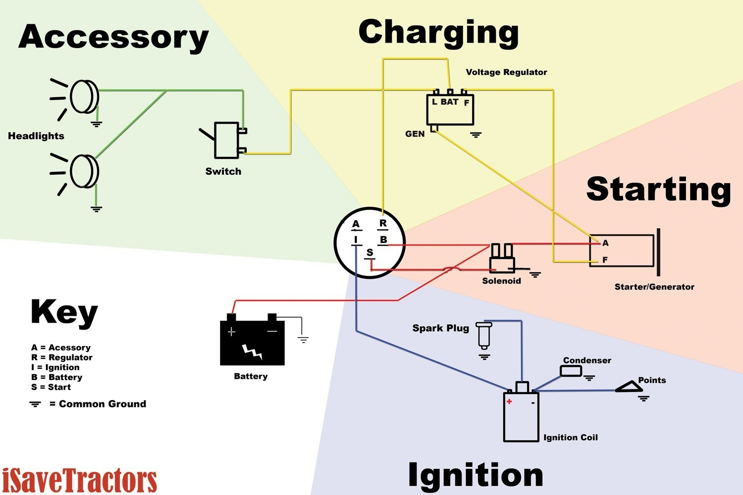
- Battery (BATT or +): This terminal connects directly to the positive terminal of the car's battery. It provides the main power source for the ignition system.
- Ignition (IGN): This terminal provides power to the car's ignition system, including the ignition coil, which creates the spark to ignite the fuel-air mixture. It's usually active in both the "Run" and "Start" positions.
- Accessory (ACC): This terminal provides power to non-essential accessories like the radio, windshield wipers, and blower motor. It's active in the "Accessory" and "Run" positions but typically not in the "Start" position to conserve power for starting.
- Start (STR or START): This terminal provides power to the starter solenoid, which engages the starter motor to crank the engine. It's only active in the "Start" position.
- Ground (GND): *Some* switches may have a ground. This ensures the circuit is properly grounded for optimal performance. In many cases, the switch grounds through its metal casing to the vehicle's chassis.
The ignition switch itself is a multi-position rotary switch. The positions are typically:
- Lock: Steering wheel is locked, and all circuits are off.
- Accessory: Battery power to ACC circuit for radio, etc.
- Run: Power to the ignition and other circuits necessary for running the car.
- Start: Power to the starter solenoid to start the engine.
Understanding Schematic Symbols
Schematic diagrams use a standardized set of symbols to represent electrical components and connections. Deciphering these symbols is essential for understanding the diagram. Here are some common symbols you'll encounter:
- Solid Lines: Represent wires. The thickness of the line usually doesn't indicate wire gauge in these simpler diagrams, but more complex drawings might use line thickness to reflect the current carrying capability.
- Dotted Lines: Often indicate wires that are optional or present only in specific vehicle configurations.
- Circles: Can represent terminals, connections, or splices.
- Rectangles: Frequently used to represent components like relays or modules.
- Zigzag Lines: Typically represent resistors.
- Colors: Wire colors are usually indicated next to the lines representing the wires (e.g., Red, Blue/White, Black). This is *extremely* important for tracing wires in your vehicle.
Understanding the connections is equally important. A dot where two lines cross indicates an electrical connection. If lines cross without a dot, it means they are simply passing over each other and are not connected electrically.
How It Works: A Simplified Circuit Flow
Here's a simplified explanation of how the 5-prong ignition switch works:
- Lock Position: No circuits are active, except perhaps the security system.
- Accessory Position: The key is turned one click, activating the ACC terminal. This powers the radio, wipers, and other accessories.
- Run Position: The key is turned further, activating both the ACC and IGN terminals. This powers the accessories and the ignition system, preparing the engine to run.
- Start Position: When the key is turned all the way to the "Start" position, the STR terminal is activated. This sends power to the starter solenoid, which engages the starter motor to crank the engine. Once the engine starts, you release the key, and it springs back to the "Run" position.
Real-World Use: Basic Troubleshooting Tips
Let's say your car won't start. Here's how you can use the diagram to troubleshoot the problem:
- Check the Battery: Ensure the battery is fully charged and the connections are clean and tight. Use a multimeter to check the voltage.
- Test the Ignition Switch: Using the diagram, identify the BATT and STR terminals on the ignition switch. Use a multimeter to check for voltage at the BATT terminal when the key is off. Then, turn the key to the "Start" position and check for voltage at the STR terminal. If there's no voltage, the switch may be faulty.
- Inspect the Wiring: Visually inspect the wiring connected to the ignition switch for any signs of damage, such as frayed wires, loose connections, or corrosion. Use the diagram to trace the wires back to the battery and starter solenoid, looking for any breaks in the circuit.
- Check Fuses: Consult your car's fuse box diagram to locate the fuses related to the ignition and starter circuits. Use a multimeter to check for continuity across the fuses. If a fuse is blown, replace it with one of the same amperage rating.
Remember, diagnosis requires patience and a systematic approach. Don't just start replacing parts randomly. Use the diagram as your guide.
Safety Precautions
Working with automotive electrical systems can be dangerous if you're not careful. Here are some important safety precautions:
- Disconnect the Battery: Always disconnect the negative terminal of the battery before working on the electrical system. This will prevent accidental shorts and electrical shocks.
- Use Proper Tools: Use insulated tools designed for automotive electrical work.
- Be Aware of Hot Components: Some components, such as the ignition coil and starter motor, can get very hot during operation. Allow them to cool down before touching them.
- Work in a Well-Ventilated Area: When working with batteries, be sure to work in a well-ventilated area to avoid inhaling harmful fumes.
- Know Your Limits: If you're not comfortable working on electrical systems, it's best to consult a qualified mechanic. The ignition coil especially stores high voltage that can be dangerous.
We have a detailed 5-prong ignition switch wiring diagram available for download. This diagram provides a comprehensive overview of the ignition system and can be a valuable tool for troubleshooting and repairs.