
Schematic 7.3 Powerstroke Wiring Diagram
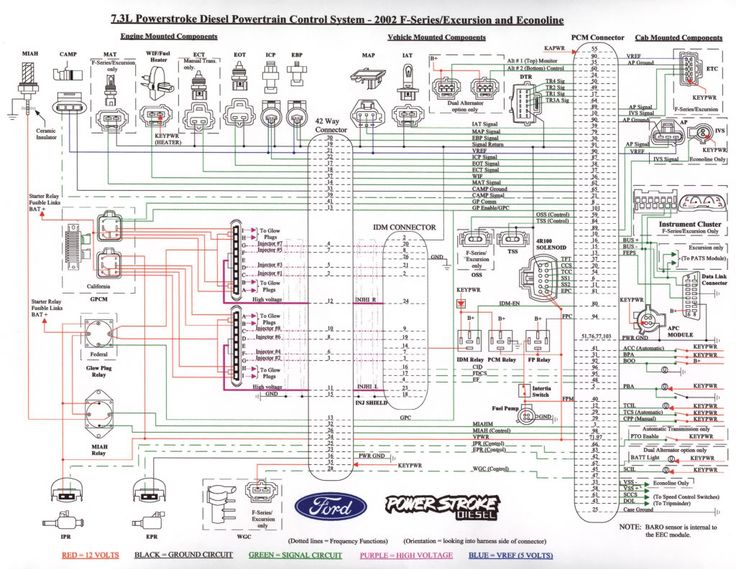
The 7.3 Powerstroke engine, a legend in the diesel truck world, is known for its robust design and relative simplicity. However, when things go wrong, navigating the intricate electrical system can be a daunting task. This is where the 7.3 Powerstroke wiring diagram becomes your best friend. This article will break down the essentials of this schematic, empowering you to understand, diagnose, and potentially repair electrical issues on your own.
Purpose of the 7.3 Powerstroke Wiring Diagram
Why bother with a wiring diagram? Several key reasons make it indispensable:
- Troubleshooting: Identifying the root cause of electrical problems, from a non-starting engine to malfunctioning sensors. Without a diagram, you're essentially guessing.
- Repairs: Locating damaged wires, connectors, or components that need replacement.
- Modifications: Safely adding aftermarket accessories, such as performance chips, gauges, or auxiliary lighting. Knowing where to tap into the existing electrical system is crucial.
- Understanding the System: Gaining a deeper understanding of how the engine's electrical system operates as a whole. This is invaluable for preventative maintenance and anticipating potential issues.
Key Specs and Main Parts Illustrated
Before diving into the diagram itself, let's familiarize ourselves with the main components typically depicted. Note that specific diagrams might vary slightly depending on the model year of your 7.3 Powerstroke (1994.5-2003):
- PCM (Powertrain Control Module): The "brain" of the engine, controlling fuel injection, ignition timing, and other critical functions. The PCM is the central hub, so a large part of the wiring diagram will involve the PCM and all the sensors reporting to it.
- IDM (Injector Driver Module): Provides the high voltage necessary to fire the fuel injectors. Located typically in the driver's side fender well.
- Fuel Injectors: Precisely deliver fuel into the cylinders. These are individually wired, and diagnosing injector issues often involves tracing wires back to the IDM or PCM.
- Sensors: Numerous sensors provide data to the PCM:
- ICP (Injection Control Pressure) Sensor: Monitors the pressure of the high-pressure oil used to actuate the injectors.
- IPR (Injection Pressure Regulator): Controls the flow of high-pressure oil, thereby regulating injection pressure.
- EOT (Engine Oil Temperature) Sensor: Measures engine oil temperature.
- IAT (Intake Air Temperature) Sensor: Measures the temperature of the air entering the engine.
- MAP (Manifold Absolute Pressure) Sensor: Measures the pressure in the intake manifold.
- CKP (Crankshaft Position) Sensor: Provides the PCM with information about engine speed and position.
- CMP (Camshaft Position) Sensor: Works in conjunction with the CKP sensor.
- Glow Plug System: Heats the cylinders for easier cold starting. Components include glow plugs, glow plug relay, and associated wiring.
- Starting System: Starter motor, solenoid, battery cables, and ignition switch wiring.
- Charging System: Alternator, voltage regulator (often integrated into the PCM), and battery wiring.
- Diagnostic Connector (OBD-II): Allows you to connect a scan tool to read diagnostic trouble codes (DTCs).
Understanding the Symbols
Wiring diagrams use a standardized set of symbols to represent components and wiring connections. Decoding these symbols is crucial to understanding the diagram:
- Lines: Represent wires. Different line styles might indicate different wire gauges or types (e.g., solid lines for power, dashed lines for ground).
- Colors: Wires are color-coded to help identify them. A color code legend is always included with the diagram (e.g., RD for Red, BK for Black, GN for Green, YE for Yellow, WH for White, BU for Blue, OR for Orange).
- Circles: Generally represent connections or splices.
- Rectangles: Can represent various components, often labeled with abbreviations (e.g., PCM, IDM, Relay).
- Ground Symbols: Indicate a connection to the vehicle's chassis ground. There are different styles of ground symbols.
- Resistors: Zigzag lines represent resistors, which limit current flow.
- Capacitors: Two parallel lines represent capacitors, which store electrical energy.
- Diodes: A triangle pointing towards a line represent a diode, which allows current to flow in only one direction.
- Switches: Represented by a line that can be open (off) or closed (on).
Pay close attention to the legend accompanying the diagram. It will define the specific meanings of the symbols and colors used in that particular schematic.
How It Works: Following the Flow of Electricity
A wiring diagram essentially maps the flow of electricity through the engine's electrical system. Start with the power source – usually the battery – and trace the circuit you're interested in. For example, if you're troubleshooting a no-start condition, you might start by tracing the power flow from the battery to the ignition switch, then to the starter solenoid, and finally to the starter motor. Look for breaks in the circuit, short circuits (where power is unintentionally connected to ground), or corroded connectors.
Most circuits are protected by fuses or fusible links. These are designed to break the circuit if there's an overload, preventing damage to components. If a circuit isn't working, the first thing to check is the fuse. Find the fuse box diagram (usually located inside the fuse box cover or in the owner's manual) and identify the fuse for the circuit you're troubleshooting. If the fuse is blown, replace it with one of the same amperage rating. If the new fuse blows immediately, there's likely a short circuit in the wiring.
The PCM uses sensors to monitor engine parameters and adjust fuel injection and ignition timing accordingly. If a sensor is malfunctioning, it can send incorrect data to the PCM, leading to performance problems. The wiring diagram helps you trace the sensor's wiring back to the PCM and check for continuity (a complete circuit) and voltage at the sensor connector. Often, a multimeter is your best friend in the diagnosing process.
Real-World Use: Basic Troubleshooting Tips
Let's consider a few common scenarios:
- Engine won't start: Use the diagram to trace the starting circuit from the battery to the starter. Check the battery voltage, ignition switch, starter solenoid, and starter motor itself.
- Glow plugs not working: Trace the glow plug circuit from the battery to the glow plug relay and then to the individual glow plugs. Check the relay's functionality and the resistance of the glow plugs.
- Check Engine Light (CEL): Use an OBD-II scanner to retrieve the diagnostic trouble code (DTC). Then, use the wiring diagram to identify the circuit related to that code and troubleshoot the associated components and wiring. Always start with the most common causes for that specific DTC.
Here are some handy general troubleshooting steps:
- Visual Inspection: Start by visually inspecting the wiring and connectors for any signs of damage, corrosion, or loose connections.
- Continuity Testing: Use a multimeter to check the continuity of wires and connections. A lack of continuity indicates a break in the circuit.
- Voltage Testing: Use a multimeter to check for proper voltage at various points in the circuit.
- Ground Testing: Ensure that all ground connections are clean and secure.
Safety: Respecting the Electrical System
Working with electrical systems involves inherent risks. Always disconnect the battery's negative terminal before working on any electrical component. This prevents accidental shorts and potential electric shock.
Be particularly cautious when dealing with the IDM. It generates high voltage to fire the injectors, and improper handling can result in a severe shock. Allow time for the high voltage capacitors inside the IDM to discharge before handling it, and avoid touching the injector connectors while the engine is running.
Never bypass fuses or fusible links with wire. This can overload the circuit and cause a fire.
If you are unsure about any aspect of the electrical system, consult a qualified mechanic.
We have the complete 7.3 Powerstroke wiring diagram file available for download. This comprehensive resource will be invaluable for your diagnostic and repair endeavors. Reach out to us for access.