Schematic Diagram Of Air Conditioning System
Alright, let's dive into the heart of your car's cooling system with a deep dive into the schematic diagram of an air conditioning (A/C) system. Think of this diagram as the roadmap to keeping your cabin cool, a vital document whether you're troubleshooting a failing system, planning an upgrade, or just expanding your automotive knowledge. We're going to break it down like a pro, so you can feel confident navigating its intricacies.
Purpose of an A/C System Schematic Diagram
So, why bother with a schematic? Simple: it's the key to understanding, diagnosing, and repairing your A/C. Trying to fix an A/C system without a schematic is like trying to assemble a complex Lego set without the instructions. Here’s why it matters:
- Troubleshooting: Quickly identify potential problem areas (leaks, electrical faults, component failures) by tracing the system's layout.
- Repairing: Locate and replace faulty components with precision, minimizing downtime and maximizing accuracy.
- Modifying/Upgrading: Plan modifications (e.g., adding a secondary evaporator for rear passengers) safely and effectively.
- Learning: Gain a deeper understanding of the A/C system's functionality and its individual components.
Key Specs and Main Parts of an A/C System
Every A/C system diagram will showcase the main components in a car. Before we analyze the schematic symbols, let's ensure everyone is familiar with them:
- Compressor: The heart of the system, driven by the engine via a belt. It compresses the refrigerant, raising its pressure and temperature.
- Condenser: Located in front of the radiator, the condenser dissipates heat from the high-pressure refrigerant, causing it to condense into a high-pressure liquid.
- Receiver Drier/Accumulator: This component filters out moisture and debris from the refrigerant, preventing damage to the expansion valve or orifice tube and compressor. Accumulators are typically used with orifice tube systems, while receiver driers are common with TXV (thermal expansion valve) systems.
- Expansion Valve/Orifice Tube: This metering device controls the flow of high-pressure liquid refrigerant into the evaporator, causing a pressure drop and rapid expansion.
- Evaporator: Located inside the dashboard, the evaporator absorbs heat from the cabin air as the refrigerant evaporates, creating cold air. A blower motor forces air across the evaporator fins, distributing the chilled air throughout the vehicle.
- Refrigerant Lines: High-pressure and low-pressure lines connecting the components, carrying the refrigerant throughout the system.
- Pressure Switches: These sensors monitor the refrigerant pressure and can shut down the compressor to prevent damage from over-pressure or low-pressure situations.
- Blower Motor: The blower motor circulates air across the evaporator.
- Control System: The temperature and fan speed settings in the car.
Understanding Schematic Symbols
Now, to the crucial part: deciphering the schematic! A/C system diagrams use standard symbols and conventions to represent components and connections. Here's a breakdown:
Lines
- Solid Lines: Represent refrigerant lines. Thicker lines might indicate high-pressure lines, while thinner lines represent low-pressure lines.
- Dashed Lines: Usually indicate electrical wiring.
- Dotted Lines: Represent control lines (vacuum or electrical signals) or drain lines.
Colors
- Colors of the wires: Electrical wires are often color-coded. The schematic will contain a key to explain what each color represents (e.g., blue for ground, red for +12V).
- Refrigerant Line Colors: Sometimes, schematics use colors to differentiate between high-pressure and low-pressure refrigerant lines.
Icons
Each component is represented by a specific icon. Here are some common examples:
- Compressor: Often depicted as a circle with a pump symbol inside.
- Condenser: Represented as a zigzag pattern or a radiator-like symbol.
- Receiver Drier/Accumulator: Usually shown as a cylinder with a desiccant pack symbol inside.
- Expansion Valve: Depicted as a valve with a control line.
- Orifice Tube: A small restrictor.
- Evaporator: Similar to the condenser but located inside the vehicle.
- Pressure Switch: A switch symbol with a circle around it, indicating pressure activation.
- Relays: A rectangle containing a coil and switch contacts.
- Fuses: A wavy line enclosed in a rectangle.
- Ground: A series of decreasing horizontal lines, resembling an inverted pyramid.
Important Note: Always refer to the specific legend provided with your vehicle's schematic, as symbols can vary slightly between manufacturers and models.
How the A/C System Works
With the symbols decoded, let's quickly recap the A/C cycle:
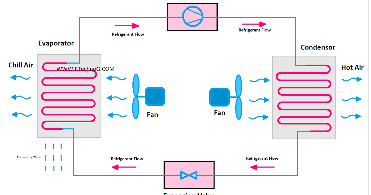
- The compressor compresses the refrigerant gas, increasing its pressure and temperature.
- The hot, high-pressure gas flows to the condenser, where it releases heat to the outside air and condenses into a high-pressure liquid.
- The high-pressure liquid passes through the receiver drier/accumulator to remove moisture and contaminants.
- The high-pressure liquid flows through the expansion valve/orifice tube, where it expands rapidly, causing a drop in pressure and temperature.
- The cold, low-pressure refrigerant enters the evaporator, where it absorbs heat from the cabin air, causing the refrigerant to boil and turn back into a gas.
- The cold air is blown into the cabin by the blower motor.
- The low-pressure refrigerant gas returns to the compressor, and the cycle repeats.
Real-World Use: Basic Troubleshooting Tips
Okay, let's use our schematic knowledge to tackle some common A/C problems:
- No Cold Air: Check the compressor clutch is engaging when the A/C is turned on. Use the schematic to trace the electrical circuit powering the clutch. A faulty relay, fuse, or pressure switch could be the culprit.
- Weak Airflow: Inspect the blower motor and resistor. The schematic will show their wiring and location. A blown resistor can cause the blower to only work on the highest setting.
- System Not Cycling: Pressure switches can prevent the compressor from engaging if the refrigerant pressure is too high or too low. Use a manifold gauge set to check the refrigerant pressure. The schematic will show the location of the high- and low-pressure service ports.
- Leaks: Visual inspection is key, but dye can be added to the refrigerant to pinpoint leaks.
Important Note: Always consult a professional for complex A/C issues, especially those involving refrigerant handling. Improper handling can be dangerous and illegal.
Safety First
A/C systems contain high-pressure refrigerant, which can cause serious injury if mishandled. Never disconnect A/C lines or components without properly evacuating the system. Refrigerant is also harmful to the environment. When working with the electrical system, always disconnect the negative battery cable to prevent electrical shock.
Also be aware that the compressor clutch and belt are moving parts and can cause serious injury if hands or tools get caught in them.
The condenser fan can also cause injury, so be careful when working near it.
Download the Diagram
To help you further, we have a sample schematic diagram available for download. This diagram is a generic representation and may not perfectly match your specific vehicle, but it will provide a solid foundation for understanding the principles we've discussed.