Sensor De Presión De Aceite Diagrama
So, you're looking to understand your oil pressure sensor diagram, eh? Smart move. Knowing how this system works can save you a lot of headaches, from diagnosing a faulty sensor to preventing engine damage. This article will break down everything you need to know, from the core components to real-world troubleshooting. We'll speak your language – technically detailed but easy to grasp.
Purpose: Why Bother with the Oil Pressure Sensor Diagram?
Let's be clear: the oil pressure sensor and its corresponding wiring diagram aren't just for show. Understanding this system is crucial for several reasons:
- Troubleshooting: A sudden low oil pressure warning light can be terrifying. A diagram helps you pinpoint the problem – is it the sensor itself, the wiring, the oil pump, or even low oil level?
- Repair: Replacing a faulty sensor or repairing damaged wiring becomes much easier with a clear understanding of the circuit. You can correctly identify connectors, wire colors, and their functions.
- Modification: Adding an aftermarket gauge or data logger? You'll need to tap into the oil pressure signal. Knowing the wiring diagram prevents accidental damage or incorrect connections.
- Learning: Even if you're not actively working on your car, understanding the oil pressure system provides valuable insight into engine health and operation.
Key Specs and Main Parts
The oil pressure system is relatively simple, but understanding the components is key. Here's a breakdown:
Oil Pressure Sensor (or Sender)
This is the heart of the system. Located on the engine block (typically near the oil filter), it measures the oil pressure within the engine's lubrication system. There are two main types:
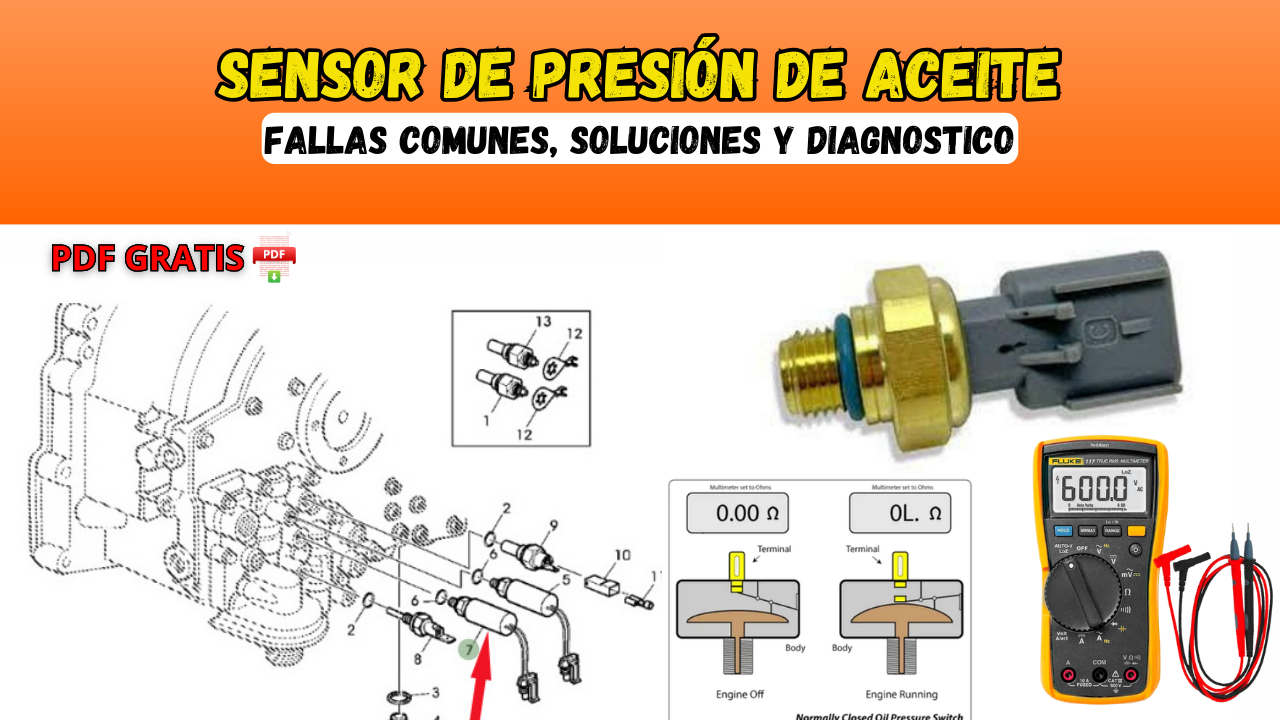
- Switch-Type Sensor: This is a simple on/off switch. When oil pressure drops below a pre-set threshold (typically around 5-7 PSI), the switch closes, grounding the circuit and illuminating the warning light on the dashboard. These are less common in newer vehicles.
- Variable Resistance Sensor (or Transducer): This type provides a variable resistance output proportional to the oil pressure. As pressure increases, resistance changes, and the ECU (Engine Control Unit) interprets this change to display the oil pressure on a gauge or as data. These are the more common type these days.
Wiring Harness
The wiring harness connects the sensor to the vehicle's electrical system. The number of wires varies depending on the sensor type:
- Switch-Type: Typically, it has a single wire connecting to the warning light circuit and the sensor grounds through the engine block.
- Variable Resistance: Commonly, they will have 3 wires, Power, Ground, and Signal.
Oil Pressure Gauge or Warning Light
This is the user interface. It displays the oil pressure reading (gauge) or illuminates a warning light when pressure is low.
ECU (Engine Control Unit)
In vehicles with variable resistance sensors, the ECU plays a vital role. It receives the signal from the sensor, interprets it, and displays the information on the gauge (if equipped) or triggers the warning light. The ECU also stores diagnostic trouble codes (DTCs) related to oil pressure issues.
Oil Pump
While not directly part of the electrical circuit, the oil pump is *the* source of oil pressure. A failing oil pump will result in low oil pressure, which the sensor will detect and trigger an alert.
Symbols: Decoding the Diagram
Understanding the symbols on the oil pressure sensor diagram is crucial for accurate diagnosis and repair. Here are some common symbols:
- Solid Lines: Represent wires or conductors.
- Dotted Lines: Often indicate shielded wiring (used to reduce electrical noise) or less critical connections.
- Ground Symbol: A triangle pointing downward or a series of horizontal lines, indicating a connection to ground (the vehicle's chassis).
- Sensor Symbol: The symbol for the oil pressure sensor varies but often resembles a circle with a resistor symbol inside (for variable resistance sensors) or a simple switch symbol (for switch-type sensors).
- Connector Symbols: Represented by squares or rectangles, often with numbered pins to indicate wire connections.
- Fuse Symbol: A squiggly line inside a rectangle, indicating a fuse for circuit protection.
- Color Codes: Wires are typically labeled with color codes (e.g., BLK for black, RED for red, GRN for green). These codes are essential for identifying the correct wires.
Important Note: Always refer to the specific wiring diagram for your vehicle model. Wiring configurations can vary significantly between manufacturers and even different model years within the same manufacturer.
How It Works: The Oil Pressure Circuit in Action
Let's trace the flow of electricity in a typical oil pressure circuit with a variable resistance sensor:
- Power Supply: The sensor receives power (typically 5V or 12V) from the vehicle's electrical system through the ECU or a dedicated power source.
- Ground: The sensor is grounded to the vehicle's chassis, completing the circuit.
- Pressure Measurement: As engine oil pressure increases, the sensor's internal resistance changes proportionally.
- Signal Transmission: The sensor sends a variable voltage signal (representing the oil pressure) back to the ECU.
- Data Interpretation: The ECU interprets the voltage signal and displays the oil pressure reading on the gauge or compares it to pre-set thresholds.
- Warning Activation: If the oil pressure falls below a critical level, the ECU illuminates the warning light on the dashboard and may also store a diagnostic trouble code (DTC).
In the case of a simple switch-type sensor, the operation is even simpler. When the oil pressure is above the threshold, the switch remains open. When pressure drops, the switch closes, grounding the circuit and turning on the warning light.
Real-World Use: Basic Troubleshooting Tips
Here are some common issues and troubleshooting steps:
- Low Oil Pressure Warning Light:
- Check Oil Level: The simplest and often overlooked step.
- Inspect the Sensor: Look for physical damage, leaks, or loose connections.
- Check Wiring: Inspect the wiring harness for damaged insulation, corrosion, or loose connectors. Use a multimeter to test for continuity and voltage.
- Test the Sensor: Use a multimeter to check the sensor's resistance or voltage output while the engine is running. Compare your readings to the manufacturer's specifications. You might need a special adapter to connect the multimeter.
- Check Oil Pressure with a Mechanical Gauge: This is the definitive test. Install a mechanical oil pressure gauge directly into the engine's oil pressure port to verify the accuracy of the sensor.
- Consider Oil Pump Condition: If all else fails, a failing oil pump may be the culprit.
- Faulty Oil Pressure Gauge Reading:
- Check Wiring: Same as above.
- Check the Sensor: Same as above.
- Check ECU (if applicable): A faulty ECU can misinterpret the sensor signal.
Remember: Always start with the simplest checks first and work your way towards more complex diagnostics.
Safety: Handling Risky Components
Working on the oil pressure system involves handling potentially hazardous components. Here are some safety precautions:
- Hot Engine: Never work on the oil pressure system while the engine is hot. Allow the engine to cool down completely before starting any work. Oil is extremely hot and can cause severe burns.
- Electrical System: Disconnect the negative battery cable before working on any electrical components to prevent accidental shorts or shocks.
- Fuel System: Be aware of the proximity of fuel lines and components. Avoid creating sparks or using open flames near the fuel system.
- Protective Gear: Wear safety glasses and gloves to protect your eyes and hands from oil and other contaminants.
- Proper Tools: Use the correct tools for the job to avoid damaging components.
- Dispose of Fluids Properly: Dispose of used oil and fluids responsibly at a designated recycling center.
In conclusion, understanding your oil pressure sensor diagram is a valuable skill for any DIY mechanic or car enthusiast. It empowers you to diagnose problems, perform repairs, and even make modifications with confidence. By understanding the components, wiring, and troubleshooting techniques, you can keep your engine running smoothly and prevent costly damage.
We have a sample oil pressure sensor diagram file available for download. It provides a visual representation of the system and can be a helpful reference tool. Contact us for access. Good luck!