Silverado 1500 Silverado Evap System Diagram
The Evaporative Emission (EVAP) control system is a critical component of your Silverado 1500, playing a vital role in reducing harmful hydrocarbon emissions. Understanding the EVAP system, particularly through its diagram, is invaluable for diagnostics, maintenance, and repairs. This article provides a detailed breakdown of the Silverado 1500 EVAP system diagram, equipping you with the knowledge to tackle EVAP-related issues like a pro.
Purpose of the EVAP System Diagram
The EVAP system diagram serves as a roadmap for understanding the system's layout, components, and interconnections. It's far more than just a picture; it's a key tool for:
- Diagnostics: Pinpointing the source of EVAP-related trouble codes (e.g., P0440, P0455, P0456).
- Repairs: Accurately identifying and replacing faulty components.
- Maintenance: Performing preventative maintenance tasks, such as inspecting hoses and connections.
- Learning: Gaining a deeper understanding of how the EVAP system functions.
- Modifications: Planning modifications that might interact with the EVAP system, ensuring compliance and proper function.
Without the diagram, you're essentially working blind, increasing the risk of misdiagnosis, unnecessary parts replacement, and potential damage. Having access to this detailed visual representation significantly streamlines the repair process.
Key Specs and Main Parts of the Silverado 1500 EVAP System
The Silverado 1500 EVAP system, like most modern automotive EVAP systems, is designed to prevent fuel vapors from escaping into the atmosphere. Key components include:
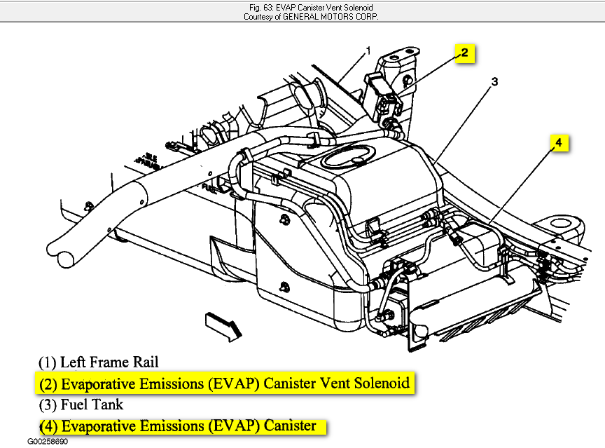
- Fuel Tank: The reservoir for fuel. Vapors from the fuel naturally form in the tank.
- Charcoal Canister: This is a crucial component. It's a container filled with activated charcoal that adsorbs (attracts and holds) fuel vapors from the fuel tank. Think of it like a sponge for gasoline fumes.
- Purge Valve (Canister Purge Solenoid Valve): This electrically controlled valve regulates the flow of fuel vapors from the charcoal canister into the engine's intake manifold to be burned during normal combustion. Its opening is controlled by the Engine Control Module (ECM).
- Vent Valve (Canister Vent Solenoid Valve): This valve controls the entry of fresh air into the charcoal canister. When the purge valve opens, the vent valve allows air to enter the canister, sweeping the fuel vapors towards the engine. It's often normally open and closes during leak tests.
- Fuel Tank Pressure Sensor (FTPS): This sensor monitors the pressure inside the fuel tank, providing crucial data to the ECM for leak detection and fuel vapor management.
- Hoses and Lines: These connect all the components, carrying fuel vapors and fresh air throughout the system.
- Fuel Cap: A seemingly simple part, but absolutely critical. It seals the fuel tank, preventing vapors from escaping. A loose or damaged fuel cap is a common cause of EVAP system leaks.
- Restrictor Orifice: A small opening in some of the lines that maintains proper flow and pressure in the system.
These components work together to trap, store, and eventually burn fuel vapors that would otherwise be released into the environment. Specific specifications, such as valve opening pressures and sensor voltage ranges, can be found in the vehicle's service manual or a dedicated EVAP system diagnostic guide.
Understanding EVAP System Diagram Symbols
EVAP system diagrams use a standardized set of symbols to represent different components and connections. Deciphering these symbols is essential for interpreting the diagram correctly.
- Solid Lines: Typically represent vacuum hoses or fuel vapor lines. The thickness of the line might indicate the diameter of the hose or the flow rate.
- Dotted Lines: Often represent electrical wiring or control signals.
- Arrows: Indicate the direction of flow (e.g., fuel vapor flow, air flow).
- Rectangles: Usually represent electrical components like solenoids, relays, or sensors.
- Circles: Can represent various components, depending on the diagram's legend. They may depict filters, orifices, or other small components.
- Color Coding: Some diagrams use color coding to differentiate between vacuum lines, fuel vapor lines, and electrical wiring. A legend will always accompany a color-coded diagram.
Pay close attention to the legend that accompanies the diagram. The legend will define the meaning of each symbol and color used in that particular diagram.
How the EVAP System Works
The EVAP system operates in several distinct stages:
- Vapor Generation: As fuel sits in the tank, it naturally evaporates, creating fuel vapors.
- Vapor Storage: These vapors are routed from the fuel tank to the charcoal canister. The activated charcoal adsorbs the vapors, preventing them from escaping into the atmosphere.
- Purging: When the engine is running and operating conditions are right (e.g., engine warmed up, not idling), the ECM commands the purge valve to open. This allows engine vacuum to draw fresh air through the vent valve, through the charcoal canister, and into the engine's intake manifold. The fresh air sweeps the stored fuel vapors from the charcoal canister, allowing them to be burned during normal combustion.
- Leak Detection: The ECM constantly monitors the EVAP system for leaks. This is typically done by sealing the system (closing both the purge and vent valves) and then using a vacuum pump (integrated into the engine or a separate diagnostic tool) to draw a slight vacuum. The FTPS monitors the vacuum level. If the vacuum drops too quickly, the ECM concludes that there is a leak in the system and will set a diagnostic trouble code.
The purge process is crucial for regenerating the charcoal canister, allowing it to continue storing fuel vapors effectively. The entire system is tightly controlled by the ECM, ensuring that fuel vapors are properly managed without negatively impacting engine performance.
Real-World Use: Basic Troubleshooting Tips
If you're experiencing EVAP-related trouble codes, here are some basic troubleshooting steps:
- Check the Fuel Cap: This is the first and easiest step. Ensure the fuel cap is properly tightened and in good condition. A loose or damaged fuel cap is a frequent culprit.
- Visually Inspect Hoses and Lines: Look for cracks, leaks, or disconnections in any of the EVAP system hoses and lines. Pay close attention to areas where hoses connect to other components.
- Listen for Vacuum Leaks: With the engine running, listen for hissing sounds near EVAP components. This could indicate a vacuum leak.
- Test the Purge Valve: You can often test the purge valve by applying vacuum to it. It should hold vacuum when de-energized and release vacuum when energized.
- Smoke Test: A smoke test is a highly effective way to find leaks in the EVAP system. A smoke machine injects smoke into the system, and you can visually identify any leaks where the smoke escapes.
- Use a Scan Tool: A scan tool can provide valuable information about the EVAP system, including sensor readings, valve status, and fault codes. This helps to narrow down the source of the problem.
Remember, diagnosing EVAP system problems can be complex, and professional diagnostic tools and expertise may be required for more challenging issues.
Safety Considerations
Working with the EVAP system involves handling fuel vapors, which are flammable and potentially hazardous. Always take the following safety precautions:
- Work in a Well-Ventilated Area: Avoid working in enclosed spaces where fuel vapors can accumulate.
- Avoid Sparks and Open Flames: Fuel vapors are highly flammable. Do not smoke or use open flames near the EVAP system.
- Wear Safety Glasses: Protect your eyes from fuel splashes and debris.
- Disconnect the Battery: Before working on any electrical components, disconnect the battery to prevent accidental shorts.
- Fuel System Pressure: Be very careful when disconnecting any fuel lines. There may still be pressure in the system. Use caution and relieve pressure if possible.
The fuel tank and fuel lines contain pressurized fuel. Improper handling can result in fire or injury. Consult a service manual for proper procedures before working on these components.
We have the complete Silverado 1500 EVAP system diagram available for download. Having this resource readily accessible will greatly assist you in your diagnostics and repairs. Access the download link below:
[Download Link Here – Replace with actual link]
By understanding the purpose, components, and operation of the EVAP system, and by utilizing the EVAP system diagram effectively, you can confidently tackle EVAP-related issues and keep your Silverado 1500 running cleanly and efficiently.