Silverado Chevy 7 Pin Trailer Wiring Diagram
Understanding the 7-pin trailer wiring diagram for your Silverado is essential for anyone who tows regularly or plans to modify their truck's electrical system for towing. Whether you're diagnosing a faulty trailer light, adding a brake controller, or simply curious about how everything connects, this knowledge empowers you to handle common towing issues efficiently and safely. This article will break down the Silverado's 7-pin wiring diagram, offering a clear explanation of each pin's function, the wiring standards, troubleshooting tips, and crucial safety precautions.
Purpose of Understanding the Silverado 7-Pin Wiring Diagram
Why bother learning this? Well, several scenarios make this knowledge invaluable:
- Repairing Trailer Lights: A common problem is a malfunctioning brake light, running light, or turn signal on your trailer. Understanding the wiring allows you to pinpoint the fault – is it the trailer wiring, the truck wiring, or a blown fuse?
- Installing a Brake Controller: If your trailer has electric brakes (common on larger trailers), you'll need to install a brake controller. The 7-pin connector provides the necessary connection for brake activation.
- Adding Auxiliary Power: Some trailers require 12V power for interior lights, refrigerators, or battery charging. The 7-pin connector includes a dedicated pin for this purpose.
- Diagnosing Electrical Issues: If you’re experiencing issues with any trailer function (lights, brakes, etc.), knowing the wiring diagram is the first step in effective troubleshooting.
- Customization and Upgrades: If you plan to add any custom electrical components to your trailer setup, a firm grasp of the wiring is crucial.
Key Specs and Main Parts
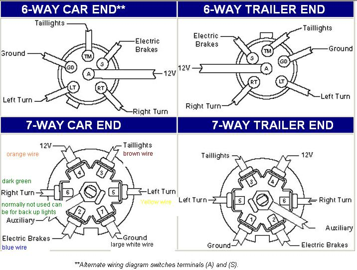
The 7-pin connector, officially known as the SAE J560 7-Way Connector, is the industry standard for connecting trailers to tow vehicles. Here's a breakdown of each pin and its function. Note that while there's a standard, slight variations *can* occur, so always double-check your specific vehicle's documentation. We'll be discussing the most common arrangement.
- Ground (White): Provides the common ground for all electrical circuits.
- Tail Lights (Brown): Powers the trailer's taillights and running lights.
- Left Turn/Stop Light (Yellow): Powers the left turn signal and brake light on the trailer.
- Right Turn/Stop Light (Green): Powers the right turn signal and brake light on the trailer.
- Electric Brakes (Blue): Connects to the electric brake controller, providing power to the trailer's brakes. The amount of power is controlled by the brake controller based on the tow vehicle's braking.
- Auxiliary Power (Black/Red): Provides a 12V DC power source for charging the trailer battery or powering other accessories. Important: This wire should be fused at the battery.
- Reverse Lights (Purple/Violet): Activates the trailer's reverse lights when the tow vehicle is shifted into reverse.
Key Components Involved:
- 7-Pin Connector (Vehicle Side): Mounted on the tow vehicle (Silverado in this case).
- 7-Pin Connector (Trailer Side): Located at the end of the trailer wiring harness.
- Wiring Harness: The set of wires connecting the vehicle-side connector to the truck's electrical system.
- Fuses and Relays: Protect the electrical circuits from overloads. You'll find these in the Silverado's fuse box. Consult your owner's manual for locations.
- Brake Controller (If Applicable): A device installed in the truck that sends power to the trailer's electric brakes.
Symbols, Lines, and Colors in the Wiring Diagram
Understanding the symbols used in a wiring diagram is critical for interpreting it correctly. Here's what to look for:
- Lines: Represent wires. Thicker lines often indicate higher current carrying capacity.
- Colors: Each wire is assigned a color to help identify it. The color code above (white, brown, yellow, green, blue, black/red, purple/violet) is standard, but always verify.
- Circles/Dots: Indicate connection points where wires are joined.
- Rectangles/Squares: Represent electrical components like relays, fuses, and switches.
- Ground Symbol: Usually a series of lines decreasing in length, indicating a connection to the vehicle's chassis ground.
- Fuse Symbol: A zig-zag line inside a rectangle, indicating a fuse protecting the circuit.
A typical Silverado 7-pin wiring diagram will show the path of each wire from the 7-pin connector to its respective connection point in the vehicle's electrical system. This includes showing the fuses and relays involved in each circuit.
How It Works: A Step-by-Step Explanation
Here's a simplified explanation of how the 7-pin system functions:
- Lights: When you turn on your Silverado's headlights, power is sent through the brown wire to the trailer's taillights. When you activate the turn signals or brake pedal, power is sent through the yellow (left) and green (right) wires to the corresponding lights on the trailer.
- Brakes: When you apply the brakes in your Silverado, the brake controller senses the deceleration and sends a proportional amount of current through the blue wire to the trailer's electric brakes. The harder you brake, the more current is sent, and the harder the trailer brakes are applied.
- Auxiliary Power: The black/red wire provides a constant 12V DC power supply to the trailer (when properly connected and fused). This can be used to charge a trailer battery or power other 12V accessories. Note: Some Silverados may have this circuit switched, meaning it's only powered when the ignition is on. Check your owner's manual.
- Ground: The white wire provides a common ground for all electrical circuits, ensuring a complete circuit for proper operation.
- Reverse Lights: When the vehicle is shifted into reverse, the purple/violet wire is energized, activating the trailer's reverse lights.
Real-World Use: Basic Troubleshooting Tips
Here are some common troubleshooting scenarios and how to address them using your understanding of the wiring diagram:
- No Trailer Lights: Check the fuses in your Silverado's fuse box. Use a multimeter to test for voltage at the 7-pin connector on the truck side. If there's no voltage, the problem is likely in the truck's wiring. If there is voltage, the problem is likely in the trailer wiring or the connector itself.
- One Light Not Working: Check the bulb first. Then, use a multimeter to test for voltage at the corresponding pin on the trailer-side connector when the light should be on. If there's no voltage, check the wiring between the connector and the light. If there is voltage, the problem is likely the wiring within the light fixture itself.
- Brakes Not Working: Verify that your brake controller is properly installed and calibrated. Check the blue wire connection at both the truck and trailer connectors. Use a multimeter to test for voltage on the blue wire when the brake controller is activated. If there's no voltage, the problem is likely the brake controller or its wiring.
- Auxiliary Power Not Working: Verify the fuse on the 12V power wire (usually located close to the battery). Check for voltage at the black/red pin on the truck-side connector with the engine running (or ignition on, depending on your setup).
Safety Precautions
Working with electrical systems can be dangerous. Follow these precautions:
- Disconnect the Battery: Before working on any wiring, disconnect the negative terminal of your Silverado's battery to prevent shorts and electrical shocks.
- Use a Multimeter: A multimeter is essential for testing voltage and continuity. Learn how to use it safely and effectively.
- Proper Wiring Techniques: Use proper crimping and soldering techniques to ensure secure and reliable connections. Avoid using wire nuts in automotive applications.
- Fuse Protection: Always use fuses of the correct amperage rating to protect circuits from overloads.
- Insulate Connections: Properly insulate all connections to prevent shorts. Use heat shrink tubing or electrical tape.
- Brake Controller Installation: If installing a brake controller, follow the manufacturer's instructions carefully. Improper installation can lead to brake failure.
- High Current Circuits: The 12V auxiliary power wire can carry significant current. Handle this circuit with extreme care to avoid shorts, which can lead to fires. Always fuse this circuit appropriately and use heavy-gauge wire.
By understanding the 7-pin trailer wiring diagram for your Silverado, you can confidently tackle many common towing issues and ensure a safe and reliable towing experience. Remember, if you're uncomfortable working with electrical systems, it's always best to consult a qualified mechanic.
We have a detailed PDF file containing the Silverado Chevy 7-Pin Trailer Wiring Diagram. Please contact us if you'd like to download it.