
Simple 2 Wire Alternator Wiring Diagram
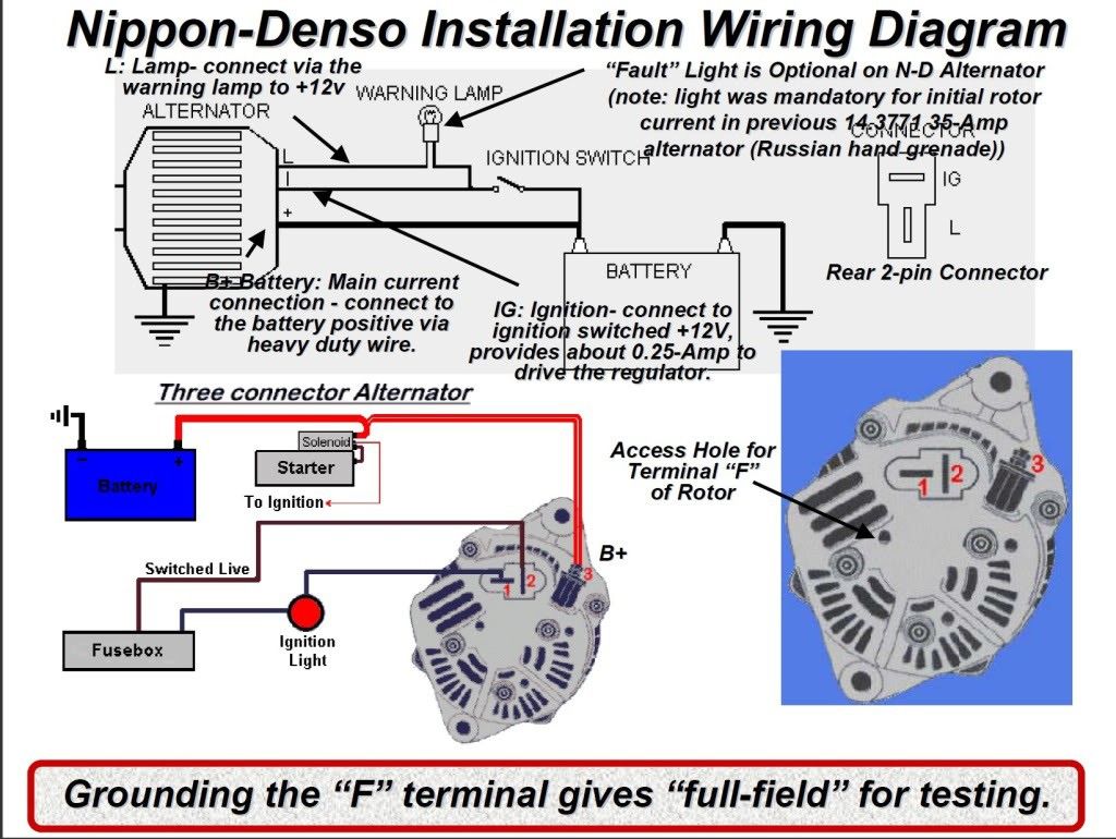
Alright, let's dive into the simple 2-wire alternator wiring diagram. This is a core skill for any experienced DIYer, car modifier, or intermediate mechanic. Understanding this setup is crucial for repairs, upgrades (like installing a one-wire alternator), or even just a deeper understanding of your vehicle's charging system. We're going to break down the diagram piece by piece, so you can confidently tackle any charging system issues.
Purpose of Understanding the 2-Wire Alternator Diagram
Why bother learning this? Well, a solid grasp of the 2-wire alternator diagram empowers you in several key areas:
- Troubleshooting: Diagnose charging problems effectively. Knowing the circuit helps isolate issues to the alternator itself, the battery, or the wiring in between.
- Repairs: Perform alternator replacements or wiring repairs with confidence. Proper wiring is crucial for a functioning charging system.
- Upgrades: Implement charging system upgrades like installing a higher amperage alternator or converting to a one-wire system.
- Custom Builds: If you're working on a custom car or engine swap, understanding this diagram is essential for integrating the charging system.
- Knowledge: Simply put, understanding how your car works is satisfying and valuable.
Key Specs and Main Parts
The 2-wire alternator system, while simple, relies on a few critical components. Here's a breakdown:
- Alternator: The heart of the charging system. It converts mechanical energy from the engine into electrical energy (AC), which is then rectified to DC.
- Voltage Regulator: Controls the alternator's output voltage to prevent overcharging the battery. In a 2-wire setup, the voltage regulator is *usually* internal to the alternator.
- Battery: Stores electrical energy and provides power to start the engine and run accessories when the engine isn't running.
- Battery Cables: Heavy-gauge wires that connect the battery to the vehicle's electrical system and the alternator. These carry significant current.
- Ignition Switch: Provides a signal to turn the alternator on and off (start the charging process).
- Wiring Harness: The collection of wires that connect all the components together.
- Fuses/Fusible Links: Crucial for safety! These protect the wiring and components from overcurrent situations.
Key specifications to be aware of include:
- Alternator Amperage: The maximum current the alternator can produce (e.g., 60 amps, 100 amps, etc.). Choose an amperage rating that meets or exceeds your vehicle's electrical needs.
- Voltage: Automotive electrical systems are typically 12V (nominal).
- Wire Gauge: The thickness of the wires. Use appropriate wire gauges for the amount of current they will carry. Thicker wires are needed for higher current loads. Consult a wire gauge chart for proper sizing.
Symbols in the Diagram
Understanding the symbols in the wiring diagram is essential for reading and interpreting it correctly. Here's a rundown:
- Solid Lines: Represent wires. The thickness of the line *sometimes* indicates the wire gauge (thicker lines = thicker wires), but always confirm with the wiring legend.
- Dashed Lines: Often indicate a ground connection or a shielded wire.
- Alternator Symbol: Typically looks like a circle with the letter "A" inside, or a stylized representation of an alternator with pulleys.
- Battery Symbol: Usually represented by a series of vertical lines, with "+" and "-" symbols indicating positive and negative terminals.
- Voltage Regulator Symbol: A small rectangle or square, often integrated within the alternator symbol.
- Fuse Symbol: A jagged line, or a small rectangle with a line through it.
- Switch Symbol: A line that breaks and connects to indicate the switch's open and closed states.
- Colors: Wire colors are often indicated using abbreviations (e.g., RED, BLK, GRN). These colors help you identify the correct wires in the vehicle.
- Ground Symbol: Typically a downward-pointing triangle or a series of horizontal lines decreasing in length. Indicates a connection to the vehicle's chassis, which serves as the return path for the electrical current.
It's important to have the *specific* diagram for your alternator and vehicle. Generic diagrams can be helpful for understanding the basic principles, but always refer to the manufacturer's diagram for accurate wiring information.
How the 2-Wire Alternator Works
The 2-wire alternator charging system is relatively simple in its operation:
- Battery Power: The battery provides initial power to the vehicle's electrical system, including the ignition system and accessories.
- Ignition Signal: When you turn the ignition key to the "ON" position, one of the wires (often a smaller gauge wire) from the ignition switch provides a signal voltage to the alternator's voltage regulator. This wire is sometimes referred to as the "exciter" wire.
- Alternator Activation: The voltage regulator senses this voltage and "excites" the alternator's field windings. This creates a magnetic field.
- Charging Process: As the engine turns the alternator's rotor, the rotating magnetic field induces an alternating current (AC) in the stator windings.
- Rectification: The AC current is then rectified (converted to DC) by a series of diodes inside the alternator.
- Voltage Regulation: The voltage regulator monitors the battery voltage and adjusts the alternator's output to maintain a stable charging voltage (typically around 13.8-14.4 volts). This prevents overcharging and damage to the battery.
- Output to Battery: The rectified DC current is then sent back to the battery through the main (larger gauge) output wire, replenishing its charge and powering the vehicle's electrical system.
- Ground Path: The alternator is grounded to the engine block, which is connected to the vehicle's chassis, providing a return path for the electrical current. A good ground connection is *essential* for proper operation.
Real-World Use: Basic Troubleshooting Tips
Here are a few basic troubleshooting tips based on the 2-wire diagram:
- No Charge: If the battery is not charging, check the following:
- Battery Voltage: Is the battery healthy? A dead or weak battery won't accept a charge.
- Alternator Output Voltage: Use a multimeter to check the voltage at the alternator's output terminal with the engine running. It should be around 13.8-14.4 volts. If it's significantly lower, the alternator may be faulty.
- Ignition Wire: Ensure the ignition wire is receiving voltage when the key is in the "ON" position. If not, check the ignition switch and wiring.
- Wiring Connections: Inspect all wiring connections for corrosion, looseness, or damage. Clean and tighten connections as needed.
- Ground Connection: Verify a good ground connection between the alternator and the engine block, and between the engine block and the chassis.
- Fuse/Fusible Link: Check the main fuse or fusible link that protects the charging circuit.
- Overcharging: If the battery is constantly boiling or showing signs of overcharge (bulging), the voltage regulator may be faulty. In most 2-wire setups, this means replacing the entire alternator.
- Battery Light On: The battery light on the dashboard indicates a problem with the charging system. It can be caused by a faulty alternator, a loose belt, or a problem with the wiring.
- Use a Multimeter: A multimeter is your best friend for troubleshooting electrical problems. Learn how to use it to measure voltage, current, and resistance.
Important Note: Before performing any electrical work on your vehicle, *always* disconnect the negative battery cable. This will prevent accidental short circuits and potential injuries.
Safety Considerations
Working with automotive electrical systems can be dangerous. Here are some crucial safety precautions:
- Disconnect the Battery: Always disconnect the negative battery cable before working on the electrical system.
- Avoid Shorts: Be careful not to short-circuit any wires or components. A short circuit can cause a fire or damage to the electrical system.
- Use Proper Tools: Use insulated tools to prevent electric shock.
- Wear Eye Protection: Wear safety glasses to protect your eyes from sparks or debris.
- Work in a Well-Ventilated Area: Batteries can produce explosive gases. Work in a well-ventilated area to prevent the buildup of these gases.
- High Current Components: The alternator and battery cables carry high currents. Be extremely cautious when working with these components. A short circuit in these areas can be very dangerous.
- Consult a Professional: If you're not comfortable working with electrical systems, consult a qualified mechanic.
Remember, safety is paramount. If you're unsure about any aspect of the wiring diagram or the repair process, seek professional assistance.
By understanding the simple 2-wire alternator wiring diagram, you'll be better equipped to diagnose, repair, and upgrade your vehicle's charging system. Don't be afraid to get your hands dirty and learn. This knowledge will save you time, money, and frustration in the long run. Always refer to your vehicle's specific wiring diagrams for accurate information.
And that's it! We've covered the essential aspects of the 2-wire alternator diagram. We have a printable version of the diagram available for download. Feel free to reach out if you have any specific questions!