
Simple 4 Wire Alternator Wiring Diagram
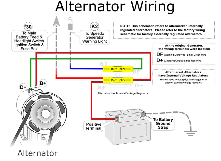
The humble alternator – the unsung hero silently churning away under the hood, keeping your battery charged and your electrical system humming. Understanding how it works, especially its wiring, is crucial for any serious DIY mechanic or car enthusiast. This article dives into the simple yet effective 4-wire alternator wiring diagram, providing you with the knowledge to troubleshoot, repair, or even upgrade your charging system.
Purpose of Understanding the 4-Wire Alternator Wiring Diagram
Why bother understanding this diagram? Several reasons. First, it's invaluable for diagnosing charging problems. A dead battery, dim lights, or strange electrical glitches could stem from a faulty alternator or its wiring. By understanding the diagram, you can systematically check connections and voltage levels to pinpoint the issue. Second, it's essential for retrofitting older vehicles or performing engine swaps. Often, the original alternator might not be compatible with the new engine, requiring a 4-wire setup for proper functionality. Third, learning about the wiring diagram helps you understand the basics of automotive electrical systems in general. It lays a foundation for tackling more complex electrical projects down the line. Finally, you can save money. Instead of blindly taking your car to a mechanic for a simple wiring issue, you can potentially fix it yourself with the right knowledge and tools.
Key Specifications and Main Parts
Before we dive into the wiring, let's review the core components and their roles. A typical 4-wire alternator setup usually involves the following:
- Alternator: The main component that converts mechanical energy from the engine into electrical energy (AC), which is then converted to DC.
- Battery: The storage device for electrical energy, providing power to start the engine and operate electrical accessories when the engine is off.
- Voltage Regulator: This critical component controls the alternator's output voltage, preventing overcharging and damage to the battery and electrical system. Some alternators have internal regulators; others require an external one.
- Ignition Switch: This is the control point that signals the alternator to start charging when the engine is running.
- Wiring Harness: The network of wires connecting all components.
While manufacturers may vary slightly, the four wires generally perform these functions:
- Battery (B+) Wire: Heavy-gauge wire connecting the alternator directly to the positive (+) terminal of the battery. This carries the main charging current.
- Sense Wire: This wire (usually thinner than the B+ wire) monitors the battery voltage at the battery itself, not at the alternator. This allows the voltage regulator to compensate for voltage drops in the wiring, ensuring the battery receives the correct charging voltage.
- Ignition (Exciter) Wire: Connected to a switched 12V source, typically from the ignition switch. This wire provides a small amount of current to "excite" the alternator and initiate the charging process when the engine is running. Without this, the alternator won't turn on.
- Ground Wire: Connects the alternator case to the chassis ground, ensuring a good electrical ground for the alternator. A poor ground can cause all sorts of charging problems.
Understanding the Wiring Diagram Symbols
Wiring diagrams use standardized symbols to represent components and connections. Here's a brief overview:
- Solid Lines: Represent wires. The thickness of the line often indicates the wire gauge (thicker lines for higher current carrying capacity).
- Dashed Lines: Might indicate a shielded wire or a wiring harness.
- Circles: Represent terminals or connection points.
- Squares or Rectangles: Often represent components like the alternator, voltage regulator, or ignition switch.
- Colors: Wires are often color-coded (e.g., red for B+, black for ground, blue for ignition). These colors are typically listed on the diagram. Follow the color codes diligently, as incorrect wiring can damage components.
- Ground Symbol: Usually a series of horizontal lines decreasing in length, indicating a connection to the chassis ground.
- Battery Symbol: Shows a positive (+) and negative (-) plate, indicating the battery's polarity.
It is critical to cross reference with the vehicle's service manual to ensure proper interpretation of the symbols as there may be variations.
How the 4-Wire Alternator System Works
Here’s a simplified explanation of the charging process:
- When you turn the ignition key to the "on" position, the ignition wire receives 12V. This exciter voltage energizes the alternator's field winding.
- As the engine starts and the alternator begins to spin, the energized field winding creates a magnetic field.
- This magnetic field interacts with the stator windings inside the alternator, generating alternating current (AC).
- The AC current is then rectified (converted) to direct current (DC) by a set of diodes within the alternator.
- The voltage regulator constantly monitors the battery voltage via the sense wire. If the voltage drops below a setpoint (typically around 13.8-14.4V), the regulator increases the current flowing through the field winding, boosting the alternator's output. Conversely, if the voltage exceeds the setpoint, the regulator reduces the field current, preventing overcharging.
- The alternator delivers the regulated DC current through the B+ wire to the battery, charging it and providing power to the vehicle's electrical system.
- The ground wire ensures a good electrical return path for the current.
Real-World Use: Basic Troubleshooting Tips
Let's say you suspect your alternator isn't charging correctly. Here are some basic troubleshooting steps, using the 4-wire diagram as your guide:
- Visual Inspection: Check all wires for corrosion, damage, or loose connections. Pay close attention to the B+ wire and the ground connection at the alternator case.
- Voltage Check at Battery: With the engine running, use a multimeter to measure the voltage at the battery terminals. A healthy charging system should read between 13.8V and 14.4V. A reading below 12.6V suggests the alternator isn't charging properly.
- Voltage Check at Alternator B+ Terminal: Measure the voltage directly at the alternator's B+ terminal. If the voltage here is significantly higher than at the battery, there's excessive voltage drop in the B+ wire, possibly due to corrosion or a loose connection.
- Ignition Wire Test: With the ignition key in the "on" position (engine off), use a multimeter to check for 12V on the ignition wire at the alternator. If no voltage is present, there's a problem with the ignition circuit.
- Ground Wire Test: Use a multimeter to check the resistance between the alternator case and the chassis ground. It should be very low (ideally close to 0 ohms). High resistance indicates a poor ground connection.
- Sense Wire Test: Check for voltage at the sense wire. It should be very close to battery voltage. A large difference here may mean a break in the sense wire circuit or a failing regulator.
Note: Always disconnect the negative battery terminal before working on any electrical components to prevent shorts and potential damage.
Safety Considerations
Working with automotive electrical systems can be dangerous. Here are some key safety precautions:
- Disconnect the Battery: Always disconnect the negative (-) battery terminal before working on any electrical components. This prevents accidental shorts and potential damage.
- Wear Safety Glasses: Protect your eyes from sparks or debris.
- Use Insulated Tools: Use tools with insulated handles to prevent electric shock.
- Be Careful Around the Battery: Batteries contain sulfuric acid, which can cause burns. Avoid contact with skin and eyes.
- Don't Work Alone: It's always a good idea to have someone nearby in case of an emergency.
- The B+ terminal is always hot. Even with the ignition off, this wire is directly connected to the battery and can deliver a significant shock or cause a short circuit if accidentally grounded.
Diagnosing and repairing an alternator issue can be challenging, but with a good understanding of the 4-wire wiring diagram and these troubleshooting tips, you'll be well-equipped to tackle the task. Remember to consult your vehicle's service manual for specific wiring diagrams and troubleshooting procedures.
We have a downloadable version of a typical 4-wire alternator wiring diagram available for you to reference. It provides a visual guide to the concepts discussed in this article. Contact us to receive the file.