
Simple Automatic Transmission Diagram
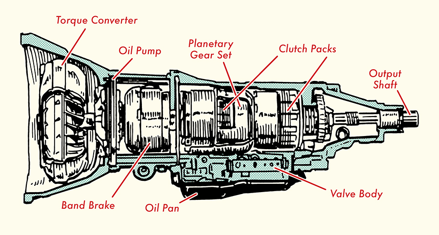
Alright, let's dive into the fascinating world of automatic transmissions, specifically looking at a simplified diagram and how to interpret it. This isn't about reinventing the wheel; it's about giving you the tools to understand your transmission's basic functions, aiding in diagnostics, repairs, and potentially even some minor modifications. We have the actual diagram available for download at the end of this article – a resource you can refer to as we go.
Purpose of a Simple Automatic Transmission Diagram
Why bother with a diagram? Well, an automatic transmission is a complex beast. A simple diagram provides a visual representation of the key components and their relationships. This is invaluable for:
- Understanding Basic Operation: Seeing the flow of power helps grasp how the transmission selects different gears.
- Troubleshooting: By knowing the components, you can narrow down potential causes of problems. For example, if you have no 3rd gear, the diagram can help pinpoint which clutches or bands are involved in that specific gear.
- Repair Preparation: Visualizing the layout can inform your repair strategy and help identify the parts you'll need.
- Educational Purposes: Maybe you just want to understand how your car works – excellent!
Key Specs and Main Parts of a Simplified Diagram
A simplified automatic transmission diagram will typically focus on the following essential parts:
- Torque Converter: This fluid coupling transfers engine power to the transmission. It multiplies torque at low speeds. Key elements within the torque converter that might be represented are the impeller (connected to the engine), the turbine (connected to the transmission input shaft), and the stator (which redirects fluid flow to increase torque multiplication).
- Planetary Gear Sets: These are the heart of the transmission, responsible for creating different gear ratios. A diagram usually shows at least one, often two, planetary gear sets. The key components of a planetary gear set are the sun gear (center), planet gears (orbiting the sun gear), and the ring gear (outer gear housing the planet gears).
- Clutches and Bands: These engage and disengage to hold specific parts of the planetary gear sets, creating the different gear ratios. Clutches are typically represented as stacked plates, while bands are shown as flexible straps that tighten around drums. The diagram will often label which clutch or band is engaged in each gear.
- Valve Body: The "brain" of the transmission, directing hydraulic fluid to the clutches and bands. The diagram might show simplified representations of key valves, such as the shift valves (which determine when to shift gears) and the pressure regulator valve (which maintains proper hydraulic pressure).
- Hydraulic Pump: Provides the necessary hydraulic pressure to operate the clutches, bands, and valve body. It's usually shown as a pump symbol connected to the torque converter or input shaft.
- Input Shaft: Transfers power from the torque converter to the planetary gear sets.
- Output Shaft: Delivers power from the planetary gear sets to the driveshaft and ultimately to the wheels.
- Transmission Fluid (ATF): The lifeblood of the transmission, providing lubrication, cooling, and hydraulic pressure. The diagram may show the fluid pathways.
Symbols Explained
Understanding the symbols is crucial to reading the diagram. Here's a breakdown of common conventions:
- Lines: Solid lines typically represent mechanical connections (e.g., shafts, linkages). Dotted or dashed lines usually indicate hydraulic lines or electrical connections.
- Arrows: Indicate the direction of power flow or fluid flow.
- Colors: While not universally standardized, colors can be used to distinguish different hydraulic circuits or electrical signals. For instance, one color might represent fluid at full pressure, while another represents fluid at reduced pressure. The diagram legend will explain the color coding.
- Circles/Squares: Often represent valves, pumps, or other hydraulic components.
- Stacked Plates: Typically denote clutches.
- Curved Bands: Represent brake bands.
How It Works – A Simplified Explanation
Let's walk through how a simplified automatic transmission works, using the diagram as a visual aid. The engine turns the torque converter, which spins the input shaft. The valve body, responding to driver input (throttle position) and vehicle speed, directs hydraulic fluid to specific clutches and bands. These clutches and bands engage and disengage, holding or releasing parts of the planetary gear sets. By holding different components stationary, the planetary gear sets create different gear ratios. For example:
1st Gear: One combination of clutches and bands engages, resulting in the highest gear reduction.
2nd Gear: Another combination engages, providing a lower gear reduction.
3rd Gear (if applicable): Yet another combination engages.
Overdrive (if applicable): A further combination engages, providing a gear ratio less than 1:1, improving fuel economy at highway speeds.
The output shaft then transmits the power at the selected gear ratio to the wheels.
Real-World Use – Basic Troubleshooting
Let's say your transmission is slipping in 2nd gear. Using the diagram, you can identify which clutch or band is responsible for 2nd gear engagement. If the diagram shows that Clutch "B" is responsible for holding the planetary gears in the correct configuration for 2nd gear, then the problem likely lies with Clutch "B" – either it's worn, the hydraulic circuit to it is leaking, or the valve controlling it is malfunctioning. Remember this is a simplified view, and further diagnostics will be needed, but the diagram has given you a starting point.
Common Issues and Diagram Use:
- Slipping: Often indicates worn clutches or bands. The diagram can help you identify which ones are used in the affected gears.
- Harsh Shifting: Could be due to valve body problems, particularly the shift valves. Check the hydraulic circuits related to those valves on the diagram.
- No Shifting: Could be a problem with the valve body, the hydraulic pump, or the clutches/bands themselves. Use the diagram to trace the power flow and hydraulic circuits.
- Complete Failure: Check the torque converter and hydraulic pump – they are critical for operation. The diagram will highlight their importance in the system.
Safety Precautions
Working on automatic transmissions can be dangerous. Here are some critical safety points:
- High Pressure: The hydraulic system operates at very high pressure. Never disconnect hydraulic lines while the engine is running or the system is pressurized. Bleed the pressure before working on the system.
- Hot Fluid: Transmission fluid gets extremely hot. Allow the transmission to cool completely before draining the fluid or working on the system.
- Heavy Components: Transmissions are heavy and awkward to handle. Use proper lifting equipment and techniques to avoid injury.
- Eye Protection: Always wear eye protection when working with hydraulic fluids or compressed air.
- Torque Converter Removal: The torque converter is filled with fluid and can be heavy. Support it properly when removing it to prevent it from falling and causing injury or damage. The stator contains complex one-way clutches, so handle it with care.
Crucially, remember that automatic transmission repair often requires specialized tools and knowledge. If you're not comfortable with any of these procedures, it's best to consult a qualified mechanic.
With the diagram as a reference, you're in a much better position to understand, diagnose, and potentially even repair your automatic transmission. Good luck, and be careful!
Now, you can download the simple automatic transmission diagram that we've been referencing throughout this article. It's a valuable tool for visualising the concepts we've discussed and will aid in your understanding of how these complex systems operate.