Simple Dodge Alternator Wiring Diagram
Alright, let's dive into the wonderfully (and sometimes frustratingly) simple world of Dodge alternator wiring diagrams. Whether you're wrestling with a no-start condition, upgrading your charging system, or just trying to understand how electricity keeps your classic Mopar humming, grasping the alternator wiring is crucial. This isn't just about blindly following wires; it's about understanding the *why* behind each connection. Consider this your comprehensive guide to demystifying that spinning electricity generator bolted to your engine.
Why This Diagram Matters: Decoding Your Dodge's Charging System
Why should you bother with a Dodge alternator wiring diagram? Several good reasons:
- Troubleshooting Charging Issues: The most common reason. A dead battery, dim headlights, or an alternator warning light scream charging system problems. The diagram is your roadmap to pinpoint the fault – is it a bad wire, a faulty regulator, or a dying alternator itself?
- Upgrading or Modifying: Swapping in a higher-output alternator for a beefier sound system or auxiliary lights? You absolutely need to understand the wiring to avoid frying components or creating a fire hazard.
- Restoring a Classic: Bringing a vintage Dodge back to life? Original wiring can be brittle, corroded, or simply missing. The diagram shows you how it was *supposed* to be connected.
- General Automotive Education: Even if everything's working perfectly, understanding the basic principles of automotive electrical systems will make you a more confident and capable car owner.
Key Specs and Main Parts: The Players in the Charging Drama
Before we crack open the diagram, let's identify the key players:
- Alternator: The heart of the charging system. It converts mechanical energy from the engine into electrical energy (alternating current, hence the name). Inside, a rotating rotor (or armature) spins within a stator, generating AC voltage. Diodes then rectify this AC voltage into DC voltage, which your car can use.
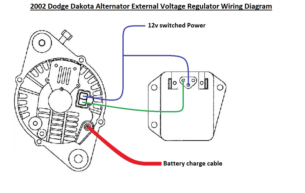
- Voltage Regulator: This is the brains. Its job is to maintain a constant voltage output from the alternator (typically around 13.5-14.5 volts) regardless of engine RPM or electrical load. Older Dodges often have external regulators, while newer models have them built into the alternator itself (internally regulated).
- Battery: The energy reservoir. It provides the initial power to start the engine and stores excess electricity generated by the alternator.
- Fuses and Fusible Links: Protective devices that prevent excessive current from damaging the wiring or components. A blown fuse is often the first sign of a problem in the charging circuit.
- Wiring Harness: The network of wires that connects all these components together. Wire gauge (thickness) is critical; thicker wires can handle higher currents.
- Ammeter or Voltmeter: Gauges that display the charging system's performance. Ammeters show the current flow (charge or discharge), while voltmeters show the voltage level. Some vehicles may have a simple charging indicator light instead.
Decoding the Diagram: Symbols and Connections
Alternator wiring diagrams, while seemingly complex at first, are just collections of symbols. Here's how to read them:
- Solid Lines: Represent wires. The thicker the line, generally the higher the current carrying capacity of the wire.
- Dotted Lines: Often represent grounding wires or less critical circuits.
- Color Codes: Wires are usually identified by color. The diagram will include a color key (e.g., "RED = Red Wire," "BLK = Black Wire," "GRN = Green Wire"). Pay close attention; using the wrong wire can cause serious damage.
- Symbols: Common symbols include:
 : Battery
 : Ground (connection to the chassis or engine block)
 : Fuse
- Boxes labeled "PCM" or "ECU": Represent the Powertrain Control Module (PCM) or Engine Control Unit (ECU), which control various engine functions, including charging in some newer vehicles.
- Terminal Identifiers: Alternators usually have terminals labeled with letters or numbers (e.g., "BAT," "FLD," "IGN," "S"). The diagram will explain what each terminal does. "BAT" is typically the main output to the battery. "FLD" is the field wire which communicates with the voltage regulator to control the amount of electricity generated. "IGN" is often a switched ignition source. "S" is often a sense wire that the regulator uses to measure voltage drop.
How It Works: The Flow of Electrons
The alternator wiring is relatively straightforward, but understanding the flow of electricity is key. Here's the basic process:
- Engine Starts: When you turn the ignition key, a small amount of current flows through the ignition circuit to the alternator's "IGN" terminal (if equipped). This activates the voltage regulator.
- Field Excitation: The voltage regulator applies a small current to the alternator's field winding (connected to the "FLD" terminal). This creates a magnetic field around the rotor.
- Alternator Spins: The engine turns the alternator's rotor via a belt. As the rotor spins within the stator, it generates AC voltage.
- Rectification: The alternator's internal diodes convert the AC voltage to DC voltage.
- Voltage Regulation: The voltage regulator monitors the output voltage. If the voltage is too low, it increases the current to the field winding, increasing the magnetic field and voltage output. If the voltage is too high, it reduces the current to the field winding.
- Charging the Battery: The DC voltage flows from the alternator's "BAT" terminal (often a heavy-gauge wire) to the positive terminal of the battery, replenishing the battery's charge.
- Powering the Car: Simultaneously, the alternator provides power to all the car's electrical components (lights, radio, etc.).
Real-World Use: Basic Troubleshooting
Armed with the diagram, here's how to tackle some common charging system problems:
- Battery Light On: Use a voltmeter to check the voltage at the battery terminals with the engine running. Should be between 13.5 and 14.5 volts. If it's lower (e.g., 12 volts or less), the alternator isn't charging properly. Check the alternator output terminal voltage first, then the battery voltage. Significant voltage drop between the two points indicates a wiring problem.
- Dead Battery: Could be a faulty alternator, a parasitic draw (something draining the battery when the car is off), or a bad battery itself. Use the diagram to check the alternator's connections and look for any signs of corrosion or damage. A parasitic draw can be identified by using a multimeter in series with the battery negative terminal and then individually removing fuses to see which circuit is causing excessive current draw.
- Overcharging: Battery boiling over? Headlights burning out prematurely? The voltage regulator is likely faulty. Replace the regulator (or the entire alternator if it's internally regulated).
- Visual Inspection: Always start with a visual inspection. Check the alternator belt tension, look for frayed or broken wires, and examine the battery terminals for corrosion. Clean and tighten any loose connections.
- Voltage Drop Testing: A voltage drop test can reveal high resistance in a circuit. Connect your multimeter leads at two ends of the circuit you want to test while the circuit is operating. Excessive voltage drop indicates a high resistance, typically caused by corrosion, loose connections, or damaged wires.
Safety First: Handle with Care!
Working with automotive electrical systems can be dangerous. Here are some safety precautions:
- Disconnect the Battery: Always disconnect the negative battery cable before working on the electrical system. This prevents accidental shorts and potential shocks.
- Use Insulated Tools: Avoid using metal tools that could short circuit components.
- Proper Wire Gauges: Never use a wire that is too thin for the application. This can cause overheating and a fire hazard. Consult the wiring diagram or a reputable source to determine the correct wire gauge.
- Avoid Shorts: Be careful not to short circuit any wires or components.
- Wear Safety Glasses: Protect your eyes from sparks and debris.
- Capacitors: Be aware that some automotive components contain capacitors that can store a charge even after the battery is disconnected. Allow time for capacitors to discharge before touching them.
- Working on the Alternator while its spinning is not recommended.
This article provides a solid foundation for understanding Dodge alternator wiring. To help you further, we have a generic Dodge Alternator Wiring Diagram available for download. This diagram provides a general layout and labeling of the major components, which should be useful as a reference point for your particular vehicle.
With a little patience and the right information (like this diagram!), you can confidently tackle your Dodge's charging system. Good luck!