
Simple Honda Motorcycle Wiring Diagram
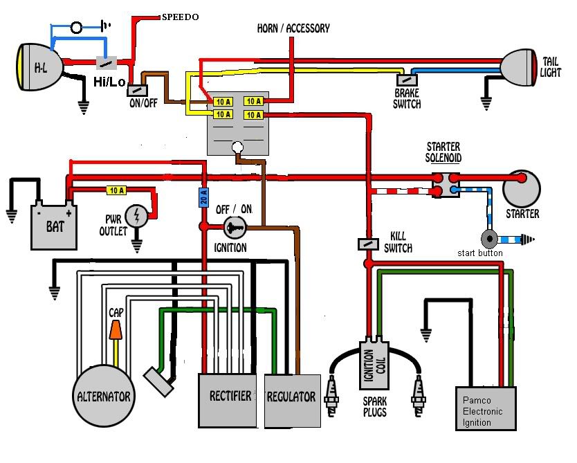
Wiring diagrams are the roadmaps of your motorcycle's electrical system. Understanding them is crucial for everything from basic maintenance to advanced modifications. This article will focus on a simplified Honda motorcycle wiring diagram, providing you with the knowledge to diagnose issues, perform repairs, and even customize your bike's electrical setup. We aim to demystify these schematics and empower you to tackle electrical tasks with confidence.
Purpose of a Motorcycle Wiring Diagram
Why bother learning about wiring diagrams? Several compelling reasons exist:
- Troubleshooting: When something electrical goes wrong – a headlight stops working, the turn signals are erratic, or the bike refuses to start – a wiring diagram helps you trace the circuit and pinpoint the faulty component.
- Repairs: Once you've identified the problem, the diagram guides you through the repair process, ensuring you replace or rewire components correctly.
- Modifications: Planning to add aftermarket accessories like LED lights, a GPS, or a USB charger? A wiring diagram is essential for safely integrating these devices into your existing electrical system. It allows you to identify appropriate power sources and ensure proper grounding.
- Understanding: Simply put, understanding how your bike's electrical system works can give you a greater appreciation for its overall design and functionality.
- Preventative Maintenance: Regularly inspecting wiring and connections, guided by the diagram, can help you identify potential problems before they lead to breakdowns.
Key Specs and Main Parts of a Simplified Honda Motorcycle Wiring Diagram
Let's break down the core components typically found in a basic Honda motorcycle wiring diagram. Keep in mind that this is a *simplified* diagram; more complex models will have additional components and circuits.
Essential Components:
- Battery: The power source for the entire electrical system. Usually a 12-volt battery.
- Ignition Switch: Controls the flow of power to various circuits. Different positions activate different components (e.g., lights, ignition).
- Fuse Box/Fuses: Protects the electrical system from overloads. Fuses are designed to blow (break the circuit) if excessive current flows through them. Fuses are rated in Amperes (Amps or A).
- Rectifier/Regulator: Converts AC voltage from the alternator to DC voltage and regulates the voltage to prevent overcharging the battery.
- Alternator (or Generator): Produces electrical power while the engine is running, recharging the battery and powering the bike's electrical components.
- Ignition System: Consists of the ignition coil, spark plugs, and associated wiring. Responsible for generating the high-voltage spark that ignites the fuel-air mixture in the engine.
- Starter Motor: Cranks the engine to initiate the combustion process.
- Lights (Headlight, Taillight, Turn Signals): Provide illumination for visibility and signaling.
- Switches (Handlebar Switches, Brake Light Switches): Control various electrical functions, such as activating lights and turn signals.
- Wiring Harness: A bundle of wires that connects all the electrical components.
- Ground (Chassis Ground): Provides a common return path for electrical current. Typically connected to the motorcycle's frame.
Understanding Wiring Diagram Symbols
Wiring diagrams use a standardized set of symbols to represent electrical components and connections. Learning these symbols is essential for interpreting the diagram.
Lines:
- Solid Lines: Represent wires. The thickness of the line *does not* typically indicate wire gauge.
- Dashed Lines: May indicate a shielded cable or a ground connection. Check the diagram's legend for specifics.
- Arrows: Can indicate the direction of current flow (though not always explicitly shown).
Colors:
Wire colors are *extremely important* for identifying specific wires in the wiring harness. Honda uses a consistent color-coding scheme. Common colors include:
- Red: Typically indicates a positive (+) power wire.
- Black: Typically indicates ground (-).
- Yellow: Often used for lighting circuits.
- Green: Another common color for ground.
- Blue: Can be used for various functions, so always verify with the diagram.
The diagram will often have a color code legend, detailing which color corresponds to which function. Be aware that wire colors may fade or become discolored over time.
Icons:
Component icons are stylized representations of the actual parts. Here are a few examples:
- Battery: Series of short and long lines, representing the positive and negative terminals.
- Resistor: A zigzag line.
- Capacitor: Two parallel lines.
- Fuse: A wavy line inside a rectangle or a simple line break symbol.
- Switch: A line connecting or disconnecting from another line.
- Ground: Often depicted as a series of descending horizontal lines, resembling an upside-down Christmas tree.
- Coil: A coil shape, indicating an inductor or ignition coil.
How It Works: Tracing a Circuit
The key to using a wiring diagram is to trace a circuit from its power source (typically the battery) through various components and back to ground. Let's imagine a simple circuit: the headlight.
- Power Source: The circuit starts at the positive terminal of the battery.
- Fuse: The power flows through a fuse, protecting the circuit from overcurrent.
- Ignition Switch: From the fuse, the power goes to the ignition switch. When the switch is turned to the "on" position, it allows current to flow to the headlight circuit.
- Headlight Switch: The power then travels to the handlebar-mounted headlight switch, which allows you to turn the headlight on or off (and sometimes switch between high and low beam).
- Headlight Bulb: The power finally reaches the headlight bulb, illuminating it.
- Ground: From the headlight bulb, the current flows back to the negative terminal of the battery through a ground wire connected to the motorcycle's frame.
By following the lines on the diagram, you can visually trace this path and understand how each component interacts.
Real-World Use: Basic Troubleshooting Tips
Here are some basic troubleshooting tips using a wiring diagram:
- No Power: If a component isn't working, start by checking the fuse. A blown fuse is a common cause of electrical problems. Use a multimeter to verify the fuse's continuity (whether it allows current to flow).
- Voltage Drop: Use a multimeter to measure the voltage at various points in the circuit. A significant voltage drop indicates a problem, such as a corroded connection or a damaged wire.
- Continuity Testing: Use a multimeter to check the continuity of wires and connections. Disconnect the battery before performing continuity tests to avoid damaging the multimeter.
- Ground Issues: Poor grounding is a frequent culprit in electrical problems. Ensure that all ground connections are clean, tight, and free of corrosion.
Example: Your headlight isn't working. Consult the wiring diagram. First, check the headlight fuse. If it's blown, replace it. If the new fuse blows immediately, there's a short circuit in the headlight wiring. Use the diagram to trace the wiring from the fuse to the headlight, looking for damaged insulation or pinched wires that might be causing a short.
Safety Considerations
Working with electrical systems can be dangerous. Always prioritize safety:
- Disconnect the Battery: Before working on any electrical component, disconnect the negative terminal of the battery to prevent accidental shocks or short circuits.
- High-Voltage Components: The ignition system contains high-voltage components. Use extreme caution when working near the ignition coil and spark plugs.
- Capacitors: Capacitors can store electrical charge even after the battery is disconnected. Discharge capacitors before handling them to avoid electric shock.
- Proper Tools: Use insulated tools designed for electrical work.
- Never Work in Wet Conditions: Water and electricity are a dangerous combination.
- Double-Check Your Work: Before reconnecting the battery, carefully double-check your wiring to ensure that everything is connected correctly.
We have a simplified Honda motorcycle wiring diagram file available for you to download. This diagram will serve as a valuable resource as you delve deeper into your bike's electrical system.