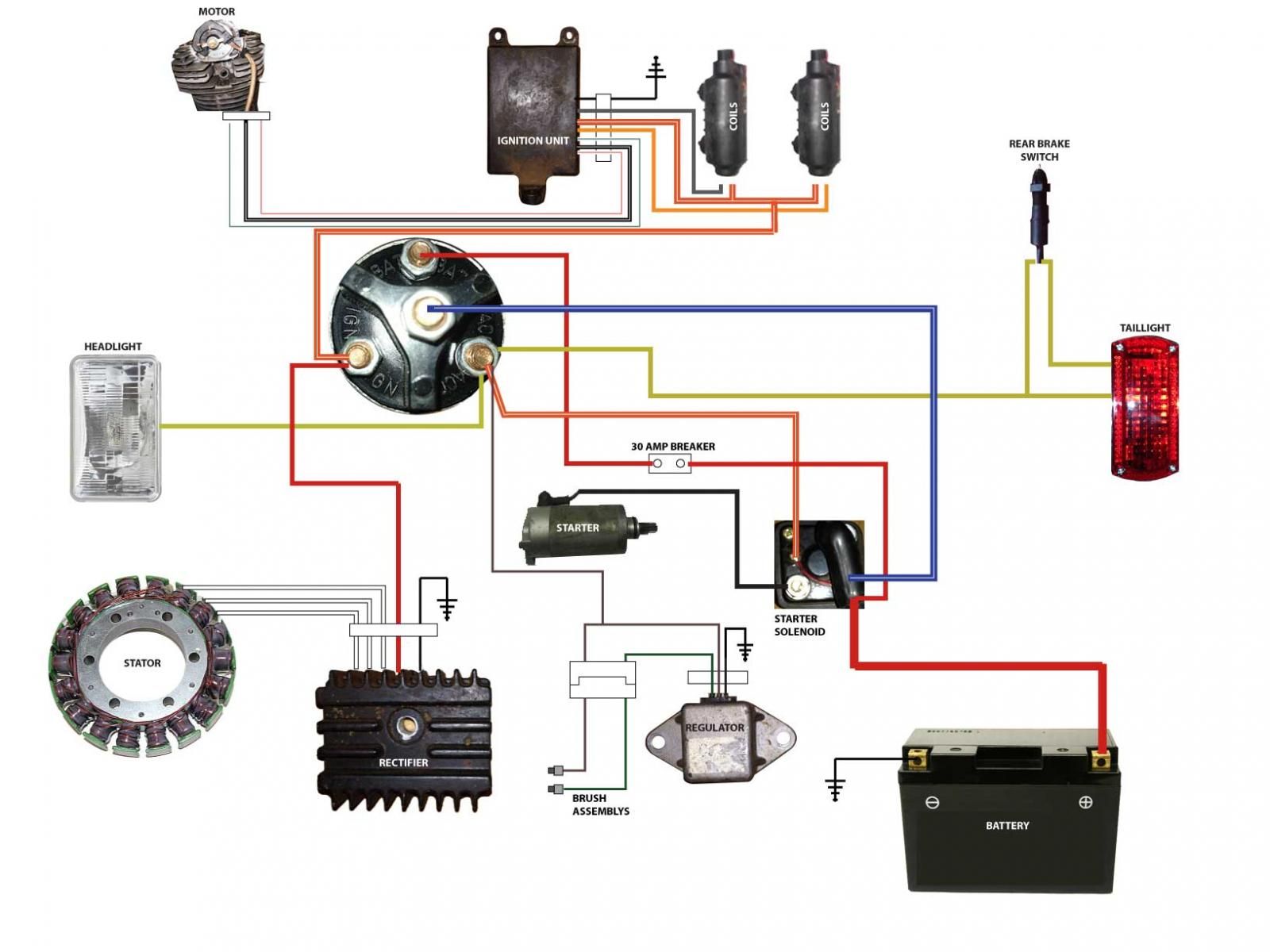
Simple Motorcycle Starter Relay Wiring Diagram
Let's talk motorcycle starter relays. They’re a crucial component, often overlooked until they fail, leaving you stranded. Understanding how they work and being able to diagnose issues with them is a valuable skill for any DIY motorcycle enthusiast. This article provides a detailed breakdown of a simple motorcycle starter relay wiring diagram, aimed at empowering you with the knowledge to troubleshoot, repair, or even upgrade your bike’s starting system.
Why This Diagram Matters
Knowing how to read a starter relay wiring diagram is essential for several reasons:
- Troubleshooting: When your bike won't start, the starter relay is a prime suspect. A diagram helps you systematically trace the circuit and identify the faulty component.
- Repair and Replacement: Replacing a faulty relay is straightforward, but understanding the wiring ensures you connect everything correctly, avoiding further damage.
- Customization and Upgrades: If you’re modifying your electrical system, adding accessories, or upgrading to a higher-capacity starter motor, understanding the relay wiring is critical for a safe and functional installation.
- Learning: It deepens your understanding of basic electrical principles and how they apply to motorcycle systems.
Key Specs and Main Parts
Before diving into the diagram, let's define the core components and specs we'll be looking at:
- Battery: The heart of the electrical system, typically a 12V DC (Direct Current) source. Its Amp-Hour (Ah) rating determines its energy storage capacity.
- Starter Relay (Solenoid): An electromechanical switch that handles the high current flow to the starter motor. It typically has a coil winding and heavy-duty contacts. Key specs include the coil voltage (usually 12V DC) and the maximum current it can handle (often measured in Amps).
- Starter Motor: The electric motor that cranks the engine. Its power is measured in horsepower (HP) or watts (W).
- Start Button: A simple switch that activates the starter relay.
- Ignition Switch: Enables the entire electrical system, providing power to the start button and other circuits.
- Fuse(s): Safety devices that protect the circuit from overcurrent. Rated in Amps, they’re designed to blow and break the circuit if the current exceeds a safe level.
- Wiring: The conductors that carry electrical current. Wire gauge (e.g., 16 AWG, 12 AWG) determines the current-carrying capacity. Thicker wires (lower gauge number) can handle more current.
Symbols – Decoding the Diagram
A wiring diagram uses standardized symbols to represent electrical components. Here's a breakdown of the common symbols you'll encounter in a simple starter relay diagram:
- Lines: Represent wires or conductors. Thicker lines often indicate wires carrying higher current.
- Solid Lines: Typically indicate positive (+) wires.
- Dashed Lines: Often indicate ground (-) or negative wires. Sometimes used for signal wires.
- Battery Symbol: A series of alternating long and short lines, representing the positive and negative terminals.
- Relay Symbol: A coil symbol (representing the electromagnet) and a switch symbol (representing the contacts).
- Switch Symbol: An open or closed contact, often with an arrow indicating the direction of movement.
- Fuse Symbol: A zigzag line enclosed in a rectangle.
- Ground Symbol: Typically three horizontal lines, decreasing in length from top to bottom, connected to a point.
- Color Codes: Wires are often color-coded (e.g., Red for positive, Black for ground, Yellow/Red for starter signal). The diagram should include a key explaining the color codes.
Example Color Codes:
- Red: +12V Battery
- Black: Ground
- Yellow/Red: Starter Relay Signal
- Green: Typically used for lights.
How It Works
The starter relay system works on a simple principle of electromagnetism. Here's the sequence of events:
- Ignition On: Turning the ignition switch on provides power to the bike's electrical system, including the start button circuit.
- Start Button Pressed: Pressing the start button completes a low-current circuit that energizes the starter relay's coil.
- Relay Activation: When the coil is energized, it creates a magnetic field. This magnetic field pulls the relay's internal contacts together, completing a high-current circuit between the battery and the starter motor.
- Starter Motor Engages: With the high-current circuit completed, the starter motor receives power and begins to crank the engine.
- Start Button Released: Releasing the start button de-energizes the relay coil, the magnetic field collapses, and the contacts separate, disconnecting the starter motor.
Essentially, the relay acts as a remotely controlled switch, allowing a small current (from the start button) to control a much larger current (to the starter motor). This protects the start button and other delicate components from the high current draw of the starter motor.
Real-World Use – Basic Troubleshooting
Here are some common problems and troubleshooting tips, using the wiring diagram as your guide:
- No Starter Motor Action:
- Check the battery voltage: Is it fully charged (around 12.6V)?
- Check the fuse: Is the starter fuse blown? Replace it with the correct amperage rating if it is.
- Check the start button: Is it working correctly? Use a multimeter to check for continuity when the button is pressed.
- Check the relay coil: With the start button pressed, is voltage reaching the relay coil terminals? If not, there's a break in the wiring.
- Check the relay contacts: If the coil is energized but the starter motor isn't turning, the relay contacts may be corroded or damaged. You can try tapping the relay lightly; sometimes this will temporarily free up stuck contacts. If this works, replace the relay.
- Check the starter motor connections: Ensure the wires connected to the starter motor are clean and securely fastened.
- Starter Motor Cranks Slowly:
- Check battery voltage: A weak battery can cause slow cranking.
- Check for voltage drop: Use a multimeter to measure the voltage at the starter motor while cranking. A significant voltage drop indicates excessive resistance in the circuit (e.g., corroded connections, undersized wires).
- Starter Motor Spins but Doesn't Engage:
- This is usually a mechanical issue with the starter motor's bendix drive or the engine's flywheel. The wiring diagram won't help with this – it requires mechanical diagnosis.
Safety – Handle with Care!
Working with electrical systems involves inherent risks. Always remember these safety precautions:
- Disconnect the Battery: Before working on any electrical component, disconnect the negative (-) battery terminal to prevent accidental shorts.
- Proper Tools: Use insulated tools to avoid shocks.
- Fuse Ratings: Never replace a fuse with a higher amperage rating. This can overload the circuit and cause a fire.
- Wire Gauge: Use wires of the appropriate gauge for the current they will carry. Undersized wires can overheat and melt.
- Seek Professional Help: If you’re uncomfortable working with electrical systems, consult a qualified motorcycle mechanic. The high current involved in the starting system can be dangerous.
Disclaimer: Starter relays can be dangerous to work on, due to the high current loads they handle. Always use caution and consult a professional for assistance if needed.
By understanding this simple starter relay wiring diagram, you're well-equipped to diagnose and repair common starting problems on your motorcycle. Remember to always prioritize safety and consult a qualified mechanic if you encounter issues beyond your expertise. With a little knowledge and the right tools, you can keep your bike running smoothly for years to come.
We have a printable version of this wiring diagram available for download. This PDF file provides a clear, easy-to-read visual representation of the starter relay circuit. It includes labeled components, color-coded wiring, and troubleshooting tips. Download it here!