
Single Wire Alternator Wiring Diagram
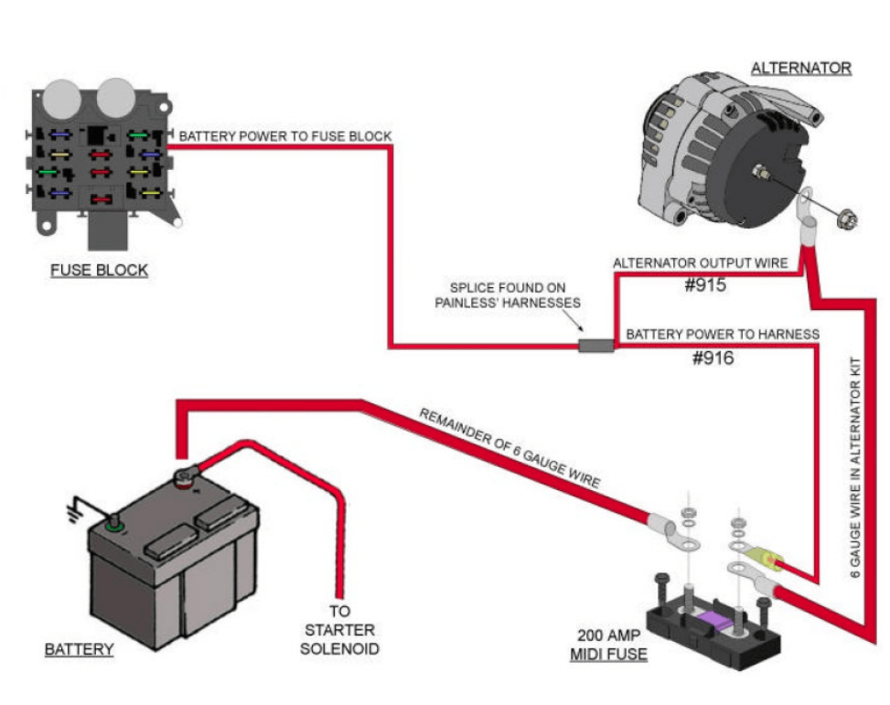
Understanding the single-wire alternator wiring diagram is crucial for anyone diving into automotive electrical systems, whether you're performing repairs, undertaking modifications, or simply expanding your knowledge of how your vehicle works. This article provides a comprehensive guide to single-wire alternator wiring, breaking down its components, functionality, troubleshooting, and safety considerations.
Purpose of Understanding the Single-Wire Alternator Diagram
The single-wire alternator, despite its name, isn't actually a one-wire system from a purely technical perspective. The "single wire" refers to the main charging wire connected directly to the battery. This configuration simplifies the wiring significantly compared to traditional multi-wire alternator setups. Understanding the wiring diagram is essential for:
- Troubleshooting Charging Issues: Identifying the source of charging problems is significantly easier with a clear understanding of the wiring layout.
- Upgrading or Replacing an Alternator: Knowing the wiring specifications ensures proper installation and prevents damage to the electrical system.
- Custom Automotive Projects: For projects involving engine swaps or custom builds, the single-wire alternator offers a clean and straightforward wiring solution.
- Learning Automotive Electrical Systems: Studying the diagram provides a solid foundation for understanding more complex automotive electrical systems.
Key Specifications and Main Parts
Let's examine the essential components of a single-wire alternator system. While the setup is simplified, each component plays a critical role.
- Alternator: The heart of the system, responsible for converting mechanical energy from the engine into electrical energy. Internal components include the rotor, stator, rectifier, and voltage regulator. Single-wire alternators typically have an internally regulated voltage regulator.
- Voltage Regulator: This component maintains a constant output voltage (typically around 13.5-14.5 volts) to prevent overcharging the battery. In single-wire alternators, the regulator is internal.
- Battery: The energy storage device for the vehicle. It provides the initial current to start the engine and supplements the alternator when electrical demands exceed the alternator's output.
- Charging Wire (Main Wire): This heavy-gauge wire connects the alternator's output terminal directly to the battery's positive terminal or a junction point connected to it. It carries the charging current.
- Ground Wire: A wire (typically connected from the alternator casing to the engine block or chassis) that provides a solid ground connection. While the name suggests a "single wire" system, a good ground is absolutely essential.
- Fuse/Fusible Link (Optional but Highly Recommended): A protective device placed in the charging wire to prevent damage from short circuits or overloads. This is crucial for safety.
Symbols and Wiring Diagram Explanation
Understanding the common symbols in a single-wire alternator wiring diagram is fundamental to interpreting the layout:
- Solid Lines: Represent wires. The thickness of the line often corresponds to the wire gauge (thicker lines indicate larger gauge wires).
- Dashed Lines: Might represent optional connections, grounds, or internal connections within the alternator.
- Battery Symbol: A stylized representation of the battery, typically with "+" and "-" signs indicating the positive and negative terminals, respectively.
- Alternator Symbol: Often a circle with "ALT" or a stylized representation of an alternator within it. The output terminal will be clearly indicated.
- Ground Symbol: Usually three horizontal lines decreasing in size, indicating a connection to the vehicle's chassis (ground).
- Fuse Symbol: A wavy line or a rectangle with a line through it. It indicates a fuse or fusible link.
Wire Colors: While not standardized across all manufacturers, some common color conventions apply:
- Red: Typically indicates a positive connection, especially the main charging wire.
- Black: Generally represents ground.
How It Works
The operation of a single-wire alternator system is relatively straightforward. When the engine starts, the alternator begins to spin, driven by a belt connected to the engine's crankshaft. As the rotor within the alternator spins, it generates an alternating current (AC) in the stator windings. The rectifier converts this AC to direct current (DC), which is the type of electricity required by the vehicle's electrical system. The internal voltage regulator monitors the battery voltage and adjusts the alternator's output to maintain a constant charging voltage. The charging current then flows from the alternator, through the main charging wire, to the battery, replenishing its charge and powering the vehicle's electrical components. Unlike standard alternators, which require an exciter wire to initially "turn on," single-wire alternators are designed to self-excite at a certain RPM. This means that they will start charging once the engine reaches a specific speed. Some may require a brief rev of the engine upon startup to begin charging.
Real-World Use: Basic Troubleshooting Tips
When troubleshooting charging issues with a single-wire alternator, consider the following:
- Check the Battery Voltage: Use a multimeter to measure the battery voltage with the engine off and then with the engine running. With the engine running, the voltage should be higher (around 13.5-14.5 volts) indicating the alternator is charging. A voltage lower than 13.5V suggests a potential problem with the alternator, wiring, or voltage regulator.
- Inspect the Charging Wire: Look for signs of damage, corrosion, or loose connections. Ensure the wire is properly connected to both the alternator and the battery.
- Verify the Ground Connection: A poor ground connection can cause a variety of electrical problems. Ensure the ground wire is securely attached to a clean, unpainted surface on the engine block or chassis. Use a multimeter to check for voltage drop between the alternator casing and the battery negative terminal; it should be close to zero.
- Check the Fuse/Fusible Link: If the charging system is completely dead, check the fuse or fusible link in the charging wire. If it's blown, replace it with one of the same amperage rating.
- Alternator Function Test: Most auto parts stores can perform a free alternator test to determine if the alternator itself is functioning properly.
Common Issues:
- Overcharging: Typically caused by a faulty voltage regulator.
- Undercharging: May be due to a worn alternator, loose belt, or poor connections.
- No Charging: Could be a blown fuse, bad alternator, broken wire, or poor ground.
Safety Considerations
Working with automotive electrical systems involves inherent risks. Remember these safety precautions:
- Disconnect the Battery: Always disconnect the negative battery cable before working on the charging system to prevent accidental short circuits.
- Wear Safety Glasses: Protect your eyes from sparks and debris.
- Avoid Touching Bare Wires: Energized wires can deliver a dangerous electric shock.
- Use Insulated Tools: When working near electrical connections, use tools with insulated handles.
- The Alternator Output is High Current: Shorting the alternator output can cause significant damage and potentially start a fire. Use extreme caution when working around the charging wire.
- Be Careful with the Engine Fan: Avoid getting your hands or clothing caught in the engine fan while the engine is running.
- If you are not comfortable working with electrical systems, consult a qualified mechanic.
Understanding the single-wire alternator wiring diagram empowers you to diagnose and address charging system issues confidently. By following the guidelines outlined in this article, you can safely and effectively maintain your vehicle's electrical system.
We have a detailed, downloadable single-wire alternator wiring diagram available. Contact us to request the file; it provides a visually clear representation to aid in your understanding and troubleshooting.