Spark Plug Diagram Good Or Bad
Alright, let's dive into spark plug diagrams. Whether you're diagnosing a misfire, swapping plugs for performance gains, or just trying to better understand your engine, knowing how to interpret a spark plug diagram is absolutely essential. Think of it as a roadmap to a crucial component of your car's combustion process. We'll break down the key parts, symbols, how they function, and even some troubleshooting tips. We even have the actual diagram file for you to download, but understanding what you're looking at is key!
Purpose of a Spark Plug Diagram
The primary purpose of a spark plug diagram is to provide a detailed visual representation of a spark plug's construction and operation. This isn't just a picture; it's a technical document that serves several important functions:
- Repair and Maintenance: When you're diagnosing engine problems like misfires, fouled plugs, or poor performance, the diagram helps you understand how the plug is supposed to function. You can compare a suspected faulty plug to the diagram to identify deviations or damage.
- Learning and Understanding: For the DIY mechanic, a diagram is invaluable for learning about the internal components of a spark plug and their roles in ignition. It demystifies the process and gives you a deeper understanding of engine operation.
- Modification and Upgrades: If you're considering upgrading your spark plugs for better performance (e.g., using iridium or platinum plugs), the diagram can help you understand the differences between different types and choose the right one for your needs. It can also show you how different plug characteristics can impact your engine.
Key Specs and Main Parts
A typical spark plug diagram will highlight the following components and specifications. Understanding these is fundamental to diagnosing spark plug issues.
Main Parts:
- Terminal: The top of the spark plug where the spark plug wire or coil-on-plug unit connects. This is where the high-voltage electricity enters the plug.
- Insulator: Typically made of ceramic, this crucial component prevents the high-voltage electricity from grounding out and directs it to the electrode. Look for cracks or damage in the insulator. A cracked insulator can cause the spark to short-circuit to the engine head, causing a misfire.
- Ribs (Insulator Ribs/Corrugations): These increase the surface area and electrical resistance of the insulator, further preventing voltage leakage. These are the wavy sections you can see on the outside of a plug.
- Metal Shell: The outer metal body of the spark plug, which is threaded to screw into the cylinder head. This provides mechanical strength and grounding for the plug.
- Gasket/Seat: Located at the base of the metal shell, this provides a tight seal between the spark plug and the cylinder head, preventing combustion gases from escaping.
- Center Electrode: The electrode located in the center of the spark plug, insulated from the shell. This is where the spark originates.
- Ground Electrode (Side Electrode): A metal strap attached to the metal shell that bends over the center electrode, forming the spark gap.
- Spark Gap: The distance between the center electrode and the ground electrode. This gap is crucial for proper ignition and must be within the manufacturer's specifications. A diagram will often specify the ideal gap.
- Resistor (Optional): Some spark plugs have a built-in resistor to suppress radio frequency interference (RFI) and prevent damage to sensitive electronic components.
Key Specs (Example):
- Thread Size: (e.g., 14mm) - The diameter of the threaded portion of the spark plug.
- Reach: (e.g., 19mm) - The length of the threaded portion of the spark plug. It's crucial to use the correct reach to avoid piston damage or improper combustion.
- Heat Range: (e.g., 6) - A numerical rating indicating how quickly the spark plug transfers heat away from the combustion chamber. Choosing the correct heat range is critical for engine performance and longevity. Too hot, and you risk pre-ignition; too cold, and you risk fouling.
- Gap: (e.g., 0.040 inches) - The specified distance between the center and ground electrodes. This is often critical to proper ignition and is usually spec'd on a sticker in your engine bay.
Symbols Explained
Spark plug diagrams use various symbols to represent different components and characteristics. While there isn't a universally standardized set of symbols, here are some common ones:
- Lines: Solid lines typically represent the physical boundaries of the spark plug components. Dashed lines may indicate internal features or hidden components.
- Colors: Colors are often used to differentiate between different materials, such as ceramic (insulator), metal (shell), and conductive materials (electrodes). A color key is usually provided with the diagram.
- Arrows: Arrows may indicate the direction of electrical current flow or the path of heat dissipation.
- Numerical Labels: Numbers are used to identify specific components, which are then explained in a corresponding legend or description.
The tolerance, that is, the acceptable range of deviation from the specification, is also often included. For instance, the spark gap may have a tolerance of +/- 0.002 inches.
How It Works
Understanding how a spark plug works is vital for interpreting a diagram and diagnosing issues. Here's a simplified explanation:
- High Voltage: The ignition coil (or coil-on-plug unit) generates a high-voltage electrical pulse (typically 12,000 - 45,000 volts).
- Current Flow: This high-voltage current travels through the spark plug wire (or directly into the coil-on-plug unit) and enters the spark plug at the terminal.
- Spark Formation: The voltage builds up at the center electrode. When the voltage reaches a sufficient level, it overcomes the resistance of the air gap between the center and ground electrodes, creating an electrical spark.
- Ignition: This spark ignites the air-fuel mixture in the combustion chamber, initiating the combustion process that drives the piston.
- Heat Dissipation: The spark plug must dissipate heat generated during combustion to prevent pre-ignition or detonation. The heat range of the spark plug determines its ability to do this.
Real-World Use: Basic Troubleshooting
Here's how a spark plug diagram can help you troubleshoot common problems:
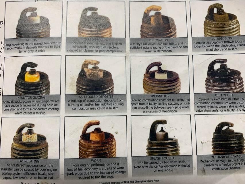
- Fouled Plugs: If a spark plug is covered in carbon deposits (black and sooty), oil, or fuel, the diagram can help you understand why. For example, excessive carbon buildup might indicate a rich air-fuel mixture, while oil fouling suggests worn piston rings or valve seals.
- Cracked Insulator: A visual inspection using the diagram as a reference will immediately reveal a cracked insulator. This often causes misfires because the high voltage leaks through the crack instead of jumping the gap.
- Worn Electrodes: The diagram shows the original shape and size of the electrodes. If the electrodes are excessively worn or rounded, the spark gap will be too wide, requiring more voltage to jump the gap, which can lead to misfires.
- Incorrect Gap: Use a feeler gauge and compare the gap to the specification in the diagram (or your car's manual). An incorrect gap can cause poor performance, misfires, and even engine damage. Always check the gap before installing new spark plugs!
Safety
Working with spark plugs involves high voltage, so safety is paramount:
- Disconnect the Battery: Always disconnect the negative battery terminal before working on spark plugs to prevent accidental electric shock.
- Wait for Engine to Cool: Never attempt to remove spark plugs from a hot engine. Allow the engine to cool completely to avoid burns.
- Use Proper Tools: Use a spark plug socket to avoid damaging the plugs or the cylinder head.
- Inspect for Damage: Carefully inspect spark plugs for cracks, chips, or other damage before installing them.
- Torque Correctly: Torque spark plugs to the manufacturer's specified torque value. Overtightening can damage the threads in the cylinder head, while undertightening can lead to leaks. Refer to your service manual for the correct torque specification.
- The ignition system components, especially the ignition coil, can store a dangerous amount of electrical charge even after the engine is turned off. Handle these components with extreme caution.
By understanding the spark plug diagram and following proper safety procedures, you can effectively diagnose and maintain your engine's ignition system.
Download the detailed spark plug diagram file to get started! (Link will be provided separately).