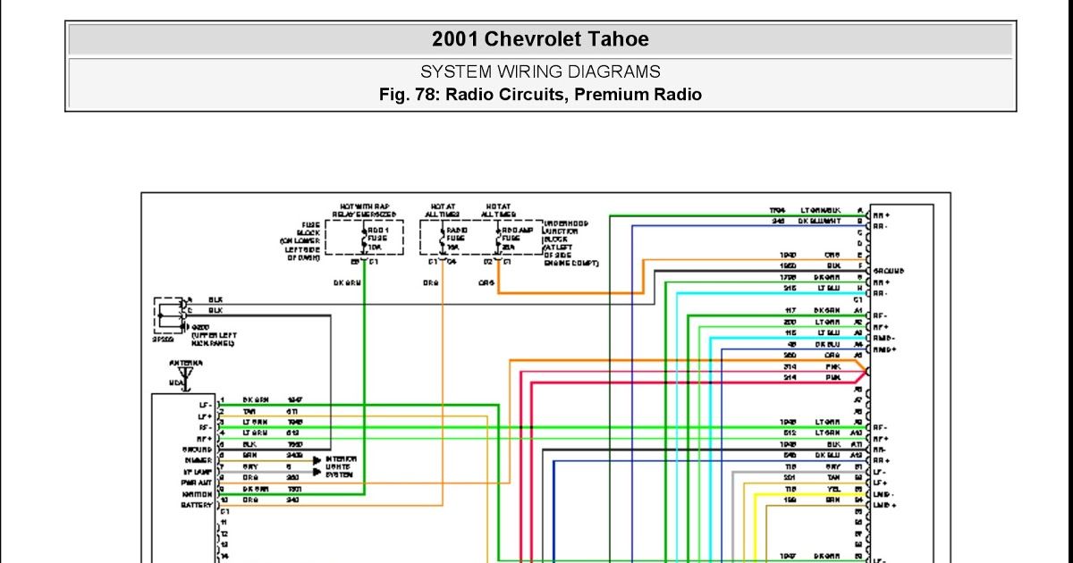
Speaker Wiring 2001 Chevy Radio Wiring Diagram
Understanding your 2001 Chevy radio wiring diagram is essential whether you're upgrading your sound system, troubleshooting speaker issues, or simply trying to understand the electrical guts of your vehicle. This isn't just some abstract diagram; it's the roadmap to your car's audio system. Having a clear understanding of it can save you money on professional installations and repairs, and give you a deeper connection to your vehicle.
Why You Need This Diagram
The 2001 Chevy radio wiring diagram serves several critical purposes:
- Speaker Replacement/Upgrades: Identifying speaker wires is crucial when installing new speakers, ensuring correct polarity (positive and negative connections) to avoid phase cancellation.
- Aftermarket Radio Installation: This is arguably the most common use. You'll need to know which wires are power, ground, antenna, and, most importantly, the speaker outputs to connect your new head unit correctly.
- Troubleshooting Audio Issues: If a speaker isn't working, or your radio suddenly cuts out, the diagram helps you trace the signal path to identify the point of failure.
- Adding Amplifiers: Integrating an external amplifier requires tapping into the existing speaker wires. The diagram allows you to do this safely and efficiently.
- Learning and Education: Simply put, studying the diagram helps you understand how a basic car audio system works, fostering a deeper understanding of automotive electronics.
Key Specs and Main Parts of the 2001 Chevy Radio Wiring
The 2001 Chevy radio wiring, like most car audio systems of that era, is a relatively straightforward setup. Here are the key components you'll find referenced in the diagram:
- Head Unit (Radio): The brain of the operation. It provides power, handles audio processing, and sends the signal to the speakers. Key connections here are:
- +12V Constant (Battery): Supplies constant power to retain radio settings and memory.
- +12V Switched (Ignition): Powers on the radio when the ignition is turned on.
- Ground: The return path for the electrical current.
- Speaker Outputs: Wires connected to each speaker in the car.
- Antenna Wire: Connects to the car's antenna.
- Speakers: The devices that convert the electrical signal into audible sound. Typically, a 2001 Chevy would have front and rear speakers.
- Wiring Harness: The bundle of wires connecting the radio to the car's electrical system. This is where all the connections happen.
- Antenna: Receives radio signals.
- Fuses: Protect the radio and other components from overcurrent. Check the fuse box diagram in your owner's manual for specific fuse locations related to the radio.
Important Specification: The speaker impedance (resistance to AC current, measured in ohms) is crucial. Most factory radios are designed for 4-ohm speakers. Using speakers with a lower impedance (e.g., 2 ohms) can overload the amplifier in the head unit and cause it to overheat or fail. Using speakers with a much higher impedance (e.g., 8 ohms) will result in very low sound volume. Always check the specifications of your replacement speakers and amplifier, if adding one, before making any connections.
Decoding the Symbols
Understanding the symbols used in the wiring diagram is vital for accurate interpretation. Here's a breakdown of common elements:
- Solid Lines: Represent wires. The thicker the line, the higher the current carrying capacity of the wire, although this is rarely differentiated in basic radio diagrams.
- Dashed Lines: Typically indicate a shielded wire, often used for the antenna cable to reduce interference.
- Color Codes: This is where the diagram becomes invaluable. Each wire is identified by a color code (e.g., RED, BLK, GRN/WHT – Green with White stripe). These codes correspond to the actual wire colors in your car. Always double-check the color codes against the actual wires in your car as variations can occur.
- Ground Symbol: Usually represented by a series of decreasing lines or a triangle pointing downwards. Indicates a connection to the vehicle's chassis for grounding.
- Component Symbols: Simplified drawings representing the radio, speakers, antenna, and other components.
- Pin Numbers: Each wire entering and exiting the radio harness is typically assigned a pin number. This allows you to identify the specific wire within the connector.
Example: A line labeled "RED/WHT Pin 5" indicates a wire that is red with a white stripe, connected to pin number 5 on the radio harness connector.
How It Works: The Signal Path
The basic operation is as follows:
- Power is supplied to the head unit from both the battery (+12V Constant) and the ignition switch (+12V Switched).
- When the ignition is turned on, the radio powers up.
- The radio receives radio signals through the antenna.
- The radio processes the audio signal (whether from the radio, CD player, or auxiliary input).
- The processed audio signal is then amplified by the radio's internal amplifier.
- The amplified signal is sent to the speakers via the speaker output wires.
- The speakers convert the electrical signal into sound waves.
Understanding this signal path allows you to isolate problems. For example, if only one speaker isn't working, the issue is likely isolated to the speaker, the wiring to that speaker, or the radio output for that speaker. If no speakers are working, the problem is likely with the power supply to the radio or the radio itself.
Real-World Use and Basic Troubleshooting
Here are a few troubleshooting scenarios where the wiring diagram is essential:
- No Power to the Radio: Check the fuses first. Then, using a multimeter, verify that you have +12V at the +12V Constant and +12V Switched wires when the ignition is on. Also, ensure you have a good ground connection.
A bad ground is a surprisingly common culprit.
- One Speaker Not Working: Check the speaker connections. Use a multimeter to test the speaker wire for continuity (a complete circuit). If the wiring is good, the speaker itself might be faulty. You can also try swapping the speaker wires with a known working speaker to see if the problem moves.
- Distorted Sound: Could be a speaker issue, but also could be a sign of a failing amplifier in the head unit, or improperly wired speakers. Check speaker impedance to ensure it matches the radio's rating.
- Radio Turns Off and On Randomly: Indicates a loose connection or a short circuit. Carefully inspect the wiring harness for any damaged or corroded wires. Check the ground connection as well.
Safety First!
Working with automotive electrical systems can be dangerous. Here are some crucial safety precautions:
- Disconnect the Battery: Before working on any electrical components, disconnect the negative terminal of the battery to prevent accidental shorts and electrical shocks.
- Use a Multimeter Safely: Learn how to use a multimeter properly to test voltage and continuity. Incorrect usage can damage the multimeter or the car's electrical system.
- Proper Wire Connections: Use proper crimping tools and connectors for making wire connections. Avoid using just electrical tape, as it can become brittle and fail over time. Solder and heat shrink tubing are preferred for a more durable connection.
- Be Aware of Airbag Wires: Never cut or tamper with any wires that are bright yellow or orange, as these are often related to the airbag system. Accidental activation of the airbag can cause serious injury.
This information provides a solid foundation for understanding your 2001 Chevy radio wiring diagram. Having the physical diagram itself is invaluable for hands-on work.
We have a downloadable version of the 2001 Chevy radio wiring diagram available. Please contact us to request the file, and be sure to specify your exact Chevy model (e.g., Silverado, Tahoe, etc.) as slight variations may exist.