Sprinter Van Mercedes Sprinter Fuse Box Diagram
So, you're diving into the electrical system of your Mercedes Sprinter van? Smart move! Understanding the fuse box diagram is absolutely crucial whether you're troubleshooting a faulty component, adding aftermarket accessories, or just trying to familiarize yourself with the inner workings of your mobile home/workhorse. This isn't just a piece of paper; it's your roadmap to preventing electrical nightmares.
Purpose of the Sprinter Fuse Box Diagram
Why does this diagram matter? Several reasons. First and foremost, it's your primary reference for diagnosing electrical issues. A blown fuse is often the culprit behind a non-functioning component, and the diagram tells you which fuse corresponds to which circuit. Second, if you're adding aftermarket lights, inverters, or other electrical upgrades, knowing which circuits are available and what their ampacity (current-carrying capacity) is crucial to avoid overloading the system and potentially causing a fire. Finally, even for general maintenance, knowing the fuse layout provides a deeper understanding of your van's electrical infrastructure.
Key Specs and Main Parts
Sprinter vans, particularly those from different model years (e.g., T1N, NCV3, VS30) and chassis configurations, can have significantly different fuse box layouts. There's no one-size-fits-all diagram. You'll typically find multiple fuse boxes: one under the driver's seat (or occasionally in the driver's footwell), and another under the hood near the battery. Some models might also have a third auxiliary fuse box. Each fuse box has a dedicated diagram, often printed on a label inside the fuse box cover itself.
Key specifications you need to pay attention to include:
- Model Year: This is absolutely critical. A diagram for a 2015 Sprinter will likely be different from a 2019 model.
- Chassis Type (e.g., 2500, 3500): While less impactful than the model year, the chassis type can influence the included options and therefore the fuse layout.
- Engine Type (Diesel vs. Gas): Though not always explicitly stated, engine type can affect some circuits.
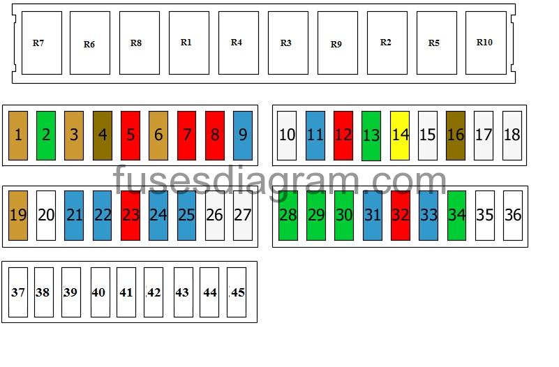
Main parts you'll see on the diagram:
- Fuse Numbers: Each fuse location is assigned a unique number.
- Circuit Description: This describes what the fuse protects (e.g., "Headlights," "Cigarette Lighter," "ABS Pump").
- Ampere Rating (Amps): This indicates the fuse's current capacity. Common values include 5A, 7.5A, 10A, 15A, 20A, 25A, 30A, and even higher. Never replace a fuse with one of a higher amperage rating without consulting a professional! This can lead to overheating and a fire.
- Fuse Type: Primarily blade-type fuses (ATO/ATC) or mini-blade fuses, and sometimes, for high-current circuits, cartridge fuses.
- Relay Information: Some diagrams also show relay locations and their corresponding functions. Relays are electromechanical switches used to control high-current circuits with a low-current signal.
Symbols – Lines, Colors, and Icons
Sprinter fuse box diagrams, thankfully, tend to be fairly straightforward. Here's a breakdown of common symbols:
- Lines: Solid lines generally indicate the main circuit path, while dashed lines might represent a ground connection or a less critical component of the circuit. Thicker lines can sometimes indicate a higher current-carrying capacity.
- Colors: Wire colors are often *not* represented on the fuse box diagram itself but can be found in the full wiring diagrams. Use wiring diagrams (available separately) in conjunction with the fuse box diagram for comprehensive electrical troubleshooting.
- Icons: Icons are often used to represent the component being protected by the fuse. For instance, a lightbulb icon for headlight fuses, a fan icon for cooling fan fuses, or a steering wheel icon for power steering fuses. Refer to the key/legend on the diagram itself for the specific meaning of each icon.
How It Works
Think of the fuse box as a distribution panel for electrical power. The battery provides the main power source. Wires carry this power to various components throughout the van. Each circuit is protected by a fuse. A fuse contains a thin wire filament designed to melt and break the circuit if the current exceeds its rated amperage. This prevents damage to the component being protected and, more importantly, prevents electrical fires.
When a component stops working, the first step is to check its corresponding fuse. If the fuse is blown (the filament is broken), replace it with a new fuse of the same amperage rating. If the new fuse blows immediately, this indicates a short circuit or an overload in that circuit. Further troubleshooting is required to identify and fix the underlying problem.
Real-World Use – Basic Troubleshooting Tips
Here's how to use the fuse box diagram for basic troubleshooting:
- Identify the Fault: Determine which component is not working (e.g., the radio, a specific light, the power windows).
- Locate the Correct Fuse Box Diagram: Use your Sprinter's owner's manual, the label inside the fuse box cover, or a reliable online source (see below) to find the diagram that matches your van's model year and configuration.
- Find the Corresponding Fuse: Using the diagram, locate the fuse that corresponds to the malfunctioning component.
- Inspect the Fuse: Remove the fuse and visually inspect it. A blown fuse will have a broken filament or a darkened appearance. Use a fuse puller (usually included in the fuse box) to avoid damaging the fuse or the fuse box.
- Test the Fuse (Optional): For a more accurate test, use a multimeter set to continuity mode. A good fuse will show continuity (a beep or a low resistance reading), while a blown fuse will show no continuity.
- Replace the Fuse: If the fuse is blown, replace it with a new fuse of the same amperage rating.
- Test the Component: After replacing the fuse, test the component to see if it's now working.
- Troubleshooting Repeated Fuse Blows: If the new fuse blows immediately or shortly after replacement, there's a persistent problem in the circuit. This requires further investigation, potentially using a multimeter to check for short circuits or excessive current draw. Consult a qualified mechanic if you're not comfortable with advanced electrical troubleshooting.
Safety – Highlight Risky Components
Working with electrical systems always involves risks. Here are some key safety considerations:
- Disconnect the Battery: Before working on any electrical components, it's highly recommended to disconnect the negative terminal of the battery. This minimizes the risk of accidental shorts and electrical shocks.
- High-Current Circuits: Be especially cautious when working with circuits that handle high current, such as the starter motor, alternator, and battery charging system. These circuits can deliver a potentially lethal shock.
- Airbag System: The airbag system is electrically controlled. Incorrectly tampering with the airbag wiring can cause the airbags to deploy unexpectedly, resulting in serious injury. Consult a professional if you need to work near the airbag system.
- Proper Tools: Use insulated tools specifically designed for electrical work.
- Read the Diagram Carefully: Understand the function of each fuse and relay before making any changes.
- Don't Guess: If you're unsure about anything, consult a qualified mechanic.
- Fire Extinguisher: Keep a fire extinguisher readily available in case of an electrical fire.
Remember, while understanding your Sprinter's fuse box diagram is incredibly useful, electrical work can be complex and dangerous. When in doubt, always seek the assistance of a qualified automotive electrician.
We've got the comprehensive Sprinter Fuse Box Diagrams for various models. You can download it for your use. Simply reach out and let us know your exact model and year, and we'll provide you with the correct document.