
Starter And Alternator Wiring Diagram
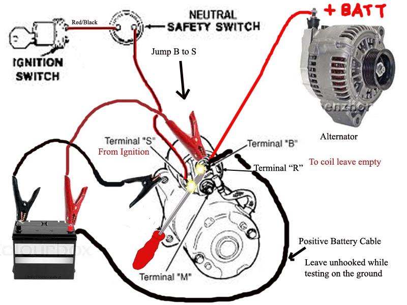
Understanding your car's electrical system can feel like deciphering a secret code, but with a grasp of the starter and alternator wiring diagram, you can unlock a crucial part of your vehicle's functionality. This isn't just about repairs; it's about empowering yourself to diagnose problems, perform modifications, and truly understand the heartbeat of your engine. Having the wiring diagram is essential. You can download it at the end of the article.
Why Bother with a Starter and Alternator Wiring Diagram?
Let's be honest, nobody *wants* to deal with electrical problems. But when your car refuses to start or the battery keeps dying, a wiring diagram becomes your best friend. Here's why:
- Troubleshooting: Quickly identify faulty components or broken wires causing starting or charging issues.
- Repairs: Ensure correct wiring when replacing a starter, alternator, or related sensors.
- Modifications: Safely add aftermarket accessories (lights, amplifiers) without overloading the system.
- Learning: Gain a deeper understanding of how your car's electrical system functions.
- Preventative Maintenance: Identify potential problem areas before they lead to breakdowns.
Key Specs and Main Parts
Before diving into the diagram, let's review the main players and their basic specifications:
Starter Motor:
- Purpose: Cranks the engine to initiate combustion.
- Key Specs: Voltage (usually 12V), Power (measured in kilowatts – kW).
- Main Parts:
- Solenoid: An electromagnetic switch that engages the starter and provides high current.
- Motor: The actual electric motor that turns the engine's flywheel.
- Bendix Drive: A gear mechanism that engages the flywheel during starting and disengages afterward.
Alternator:
- Purpose: Charges the battery and powers the electrical system while the engine is running.
- Key Specs: Voltage (usually 12V), Amperage (measured in amps – A), Regulator Type (internal or external).
- Main Parts:
- Rotor: A rotating electromagnet.
- Stator: Stationary windings that generate AC current.
- Rectifier: Converts AC current to DC current for use by the vehicle.
- Voltage Regulator: Maintains a consistent voltage output to prevent overcharging the battery.
Battery:
- Purpose: Provides initial power to start the car and acts as a voltage stabilizer.
- Key Specs: Voltage (usually 12V), Cold Cranking Amps (CCA), Amp-Hour (Ah) rating.
- Terminals: Positive (+) and Negative (-)
Wiring Harness:
- Purpose: A bundle of wires that connects all the electrical components in the car.
- Key Specs: Wire gauge (thickness), insulation type.
Fuses and Relays:
- Purpose: Protection and switching. Fuses protect circuits from overcurrent; relays are electrically operated switches.
Decoding the Symbols: Lines, Colors, and Icons
A wiring diagram uses a standardized language of symbols. Here's a breakdown:
- Lines: Represent wires. Thicker lines often indicate higher current capacity. Dashed lines may indicate a shielded cable.
- Colors: Each wire is assigned a color code (e.g., Red for power, Black for ground). This is *crucial* for tracing wires. Consult your specific diagram's legend.
- Icons: Represent components. Common icons include:
- Battery: A symbol resembling a battery with (+) and (-) markings.
- Starter Motor: Often a circle with an "M" inside.
- Alternator: Similar to the starter, but may have an "A" inside.
- Ground: Usually a series of downward-facing triangles.
- Fuses: A zig-zag line inside a rectangle.
- Relays: A square with a coil symbol and switch contacts.
- Switches: A line that can be open (off) or closed (on).
- Numbers and Letters: Often indicate wire gauge or circuit identification.
Important: Always refer to the legend or key on your specific wiring diagram. Color codes and symbols can vary slightly between manufacturers and models.
How It Works: The Electrical Flow
Let's trace the flow of electricity during starting and charging:
Starting Sequence:
- When you turn the ignition key, a small current flows to the starter solenoid.
- The solenoid acts as an electromagnetic switch, closing a high-current circuit from the battery directly to the starter motor.
- The starter motor spins, engaging the Bendix drive, which cranks the engine.
- Once the engine starts, the ignition key returns to the "run" position, disengaging the starter.
Charging Sequence:
- Once the engine is running, the alternator is driven by the engine's belt.
- The alternator generates AC current, which is then rectified (converted) to DC current.
- The voltage regulator monitors the battery's voltage and adjusts the alternator's output to maintain a consistent charging voltage (typically around 13.8-14.4V).
- The alternator provides power to the car's electrical system and charges the battery simultaneously.
The wiring diagram shows you exactly how these components are connected and the paths the current takes.
Real-World Use: Basic Troubleshooting Tips
Here's how to use the diagram to diagnose common problems:
- Car won't start:
- Check the battery voltage with a multimeter.
- Using the diagram, trace the starter circuit. Look for broken wires, loose connections, or a faulty solenoid.
- Test the starter motor directly by applying 12V (carefully!).
- Battery keeps dying:
- Check the alternator's output voltage with a multimeter while the engine is running. It should be within the specified range (13.8-14.4V).
- Look for a parasitic drain (something drawing power when the car is off). The diagram can help you isolate circuits.
- Have the battery load-tested.
- Dim headlights or flickering lights:
- Check the alternator's voltage regulator.
- Inspect the ground connections. A bad ground can cause voltage drops.
Important: When troubleshooting, always start with the simplest checks first: battery voltage, connections, and fuses.
Safety First: Handle with Care
Working with electrical systems can be dangerous. Keep these safety tips in mind:
- Disconnect the battery's negative terminal before working on any electrical components. This prevents accidental shorts.
- Never work on the electrical system with the engine running unless specifically instructed to do so for testing purposes.
- Use a multimeter to test for voltage and continuity before touching any wires.
- Wear safety glasses to protect your eyes.
- Be especially careful when working around the starter solenoid, as it carries a very high current.
- If you're unsure about anything, consult a qualified mechanic.
The alternator and starter circuits handle significant amperage, making short circuits potentially dangerous, causing fire or damage to components. Always double-check your connections and follow safety guidelines. Don't underestimate the power stored in the battery; even a short circuit can generate substantial heat and sparks.
By understanding and utilizing the starter and alternator wiring diagram, you can confidently tackle many electrical issues in your car. Remember to always prioritize safety and consult a professional if you're unsure. You now have the knowledge to start!
As promised, you can download the wiring diagram by following this link: Download Wiring Diagram