
Starter Motor Solenoid Wiring Diagram
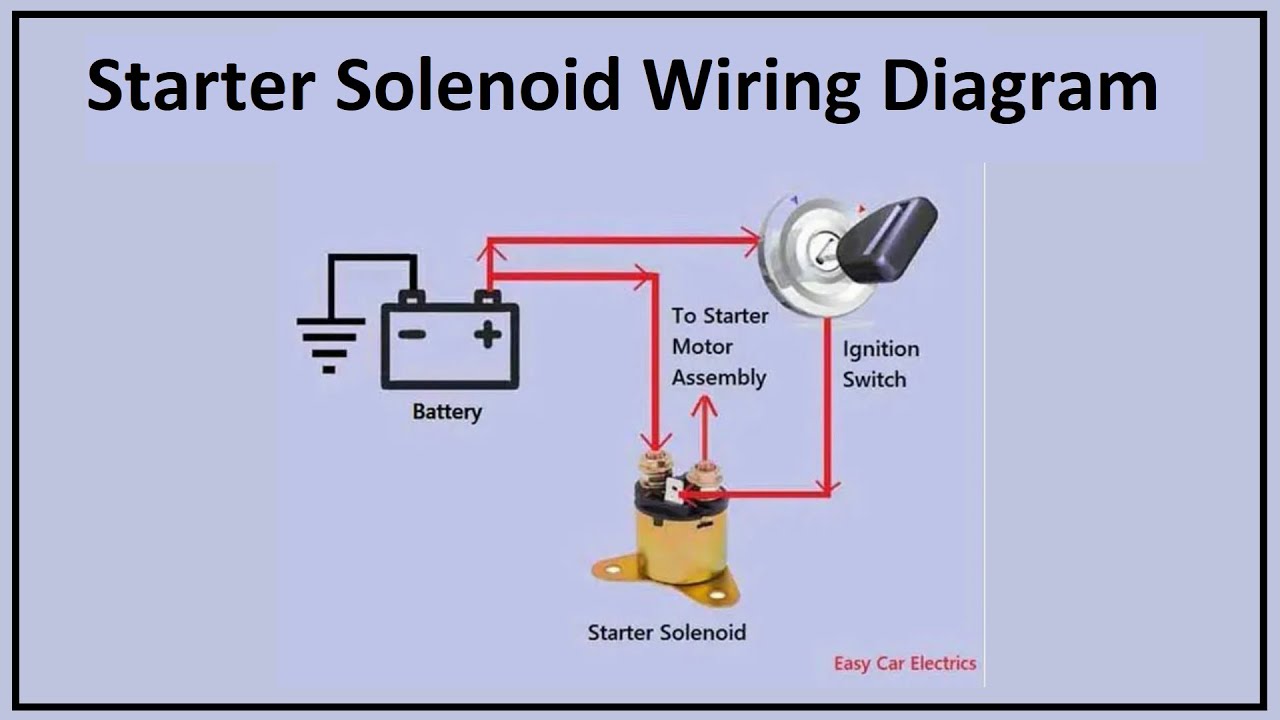
Understanding the starter motor solenoid wiring diagram is crucial for any seasoned DIY mechanic or car enthusiast looking to troubleshoot starting problems, perform modifications, or simply deepen their automotive knowledge. It's the roadmap to a reliable start every time.
Purpose: Your Guide to a Reliable Start
Why bother with a starter motor solenoid wiring diagram? Several compelling reasons exist:
- Troubleshooting Starting Issues: Diagnosing a no-start condition often leads to the starter circuit. The wiring diagram is your key to identifying faulty components, short circuits, or open circuits.
- Performing Repairs: Replacing a faulty solenoid, wiring harness, or starter motor becomes infinitely easier with a clear understanding of the electrical connections.
- Modifications and Upgrades: Whether you're installing a high-performance starter or modifying your electrical system, the diagram ensures proper integration and avoids costly mistakes.
- Educational Purposes: Understanding how the starter circuit works demystifies a critical component of your vehicle and empowers you to perform more advanced diagnostics and repairs.
Key Specs and Main Parts: The Players in the Starting Game
Before diving into the diagram itself, let's define the key components involved in the starter circuit:
- Battery: The heart of the electrical system, providing the initial power to crank the engine. Nominal voltage is typically 12V DC.
- Ignition Switch: The control center. When you turn the key, it sends a signal to activate the starter solenoid.
- Starter Solenoid: An electromagnetic switch that engages the starter motor and supplies it with high current from the battery. It typically has two main circuits:
- Control Circuit: A low-current circuit that activates the solenoid coil.
- Power Circuit: A high-current circuit that delivers power directly to the starter motor.
- Starter Motor: The electric motor that turns the engine's crankshaft, initiating the combustion process.
- Neutral Safety Switch (Automatic Transmissions): Prevents the engine from starting unless the transmission is in Park or Neutral. This is a crucial safety feature.
- Clutch Switch (Manual Transmissions): Similar to the neutral safety switch, this prevents starting unless the clutch pedal is depressed.
- Wiring Harness: A collection of wires that connect all the components together.
- Fuses and Relays: Protective devices that prevent damage from overloads or short circuits. The starter circuit typically has a high-amperage fuse.
Symbols: Deciphering the Diagram's Language
Wiring diagrams use standardized symbols to represent electrical components and connections. Understanding these symbols is essential for interpreting the diagram accurately.
- Solid Lines: Represent wires. The thickness of the line may, but not always, indicate the wire gauge (thicker lines for higher current).
- Dotted Lines: Often indicate ground connections or shielded wires.
- Circles: Can represent various components, depending on what’s inside. Common icons include:
- Battery: A series of short and long parallel lines. The longer line represents the positive (+) terminal.
- Resistor: A zig-zag line.
- Capacitor: Two parallel lines of equal length.
- Switch: A break in a line, with a lever or other symbol indicating the switch type.
- Ground: A series of horizontal lines decreasing in length, indicating a connection to the vehicle's chassis.
- Colors: Wires are often color-coded to aid in identification. Common color codes include:
- Red: Typically indicates a positive (+) power source, often directly from the battery.
- Black: Usually represents ground (negative -) connection.
- Yellow: Often used for circuits controlled by the ignition switch.
- Blue/Green/Brown: Can represent various signals or control circuits. Always refer to the specific diagram's legend.
The legend on the diagram is critical. It will define what the symbols mean for your specific vehicle. Always refer to it.
How It Works: From Key Turn to Engine Roar
The starting process, as depicted in the wiring diagram, unfolds as follows:
- Ignition Key Turned: When you turn the ignition key to the "Start" position, a signal is sent to the starter solenoid's control circuit.
- Solenoid Activation: The low-current signal energizes the solenoid's coil, creating an electromagnetic field.
- Plunger Engagement: The electromagnetic field pulls a plunger inside the solenoid. This plunger performs two crucial functions:
- Closing the Power Circuit: The plunger connects the high-current terminals, allowing battery voltage to flow directly to the starter motor.
- Engaging the Starter Motor: Simultaneously, the plunger mechanically pushes the starter motor's pinion gear into the engine's flywheel or flexplate.
- Starter Motor Cranking: The starter motor, now receiving full battery power, spins the engine's crankshaft, initiating the combustion process.
- Engine Starts: Once the engine starts, you release the ignition key, de-energizing the solenoid. The starter motor disengages from the flywheel.
The neutral safety switch (automatic) or clutch switch (manual) are incorporated into the control circuit, preventing the solenoid from activating unless the transmission is in the correct position.
Real-World Use: Basic Troubleshooting Tips
The wiring diagram is invaluable when troubleshooting starting problems. Here are a few basic tips:
- No Click, No Crank:
- Check the battery voltage and connections.
- Inspect the starter fuse and relay.
- Test the ignition switch.
- Verify the neutral safety switch or clutch switch is functioning correctly.
- Check the solenoid control circuit for voltage when the key is in the "Start" position.
- Click, But No Crank:
- This often indicates a problem with the starter motor itself or the solenoid's high-current contacts.
- Check the battery cable connections to the starter.
- Try tapping the starter motor with a hammer (gently!) while someone attempts to start the car. This can sometimes dislodge a stuck brush.
- Starter Cranks Slowly:
- Check the battery voltage.
- Inspect the battery cables for corrosion.
- The starter motor may be worn out.
Use a multimeter to test for voltage and continuity in the circuit. Always consult the wiring diagram to identify the correct test points.
Safety: Handle with Care
Working with the starter circuit involves high currents and potentially dangerous situations. Observe the following safety precautions:
- Disconnect the Battery: Always disconnect the negative (-) battery cable before working on the electrical system. This prevents accidental short circuits and potential shocks.
- Work in a Well-Ventilated Area: Battery acid can produce explosive hydrogen gas.
- Wear Safety Glasses: Protect your eyes from sparks and debris.
- Use Insulated Tools: Prevent short circuits and shocks.
- Be Careful Around the Starter Motor: The starter motor can get very hot after extended cranking.
- The High-Current Cables Are Risky: Shorting these can weld tools and cause burns. Treat them with respect.
Warning: The starter circuit is a high-current circuit. Incorrectly wiring or troubleshooting this circuit can result in electrical shock, fire, or damage to your vehicle. If you are not comfortable working with electrical systems, consult a qualified mechanic.
Armed with this knowledge and a detailed wiring diagram specific to your vehicle, you're well-equipped to tackle starter circuit repairs, modifications, and diagnostics with confidence. Remember to always prioritize safety and consult the specific wiring diagram for your vehicle model.
We have a sample starter motor solenoid wiring diagram file available. You can download it to further your understanding and use it as a reference. This will help you better visualize the concepts discussed in this article and apply them to your own projects.