
Starter Motor Wiring Diagram With Relay
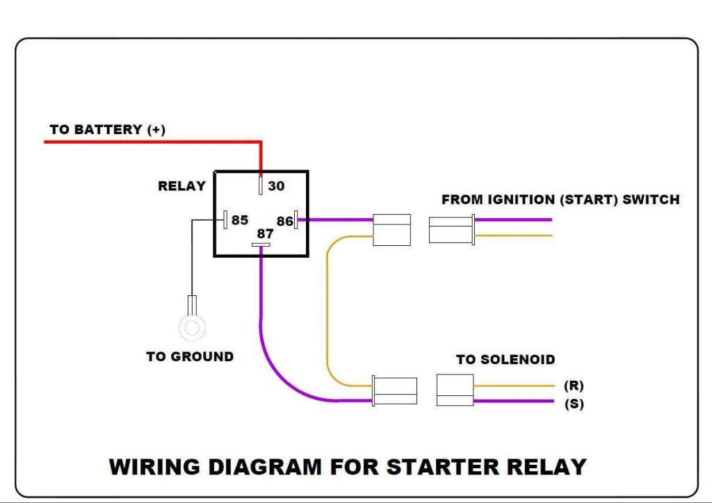
Understanding your car's starter motor circuit is essential for various reasons, from diagnosing a no-start condition to performing custom wiring modifications. This article dives into the wiring diagram of a starter motor setup utilizing a relay. Knowing how the system is wired, its key components, and how it functions enables you to troubleshoot problems effectively, perform necessary repairs, and even implement upgrades. We'll break down the intricacies of the diagram, explaining the function of each component and the significance of different wiring conventions.
Purpose of the Starter Motor Wiring Diagram with Relay
The wiring diagram serves as a roadmap for the electrical connections in your car's starting system. Specifically, using a relay in the starter circuit accomplishes several things:
- Diagnosis: Pinpointing faults when your car won't start. Is it the battery, the solenoid, the ignition switch, or something else? The diagram helps you trace the electrical path and identify the faulty component.
- Repair: Accurately reconnecting wires after repairs or component replacements. Incorrect wiring can damage the starter motor or other electrical components.
- Modification: Implementing upgrades such as remote starters, anti-theft systems, or high-torque starter motors. A relay provides a clean way to integrate these systems.
- Understanding: Gaining a deeper knowledge of your car's electrical system, allowing you to perform more advanced maintenance and repairs.
- Preventative Maintenance: Identifying potential weak points in the system before they fail, such as corroded wires or loose connections.
Key Specs and Main Parts
Before we dissect the diagram, let's identify the key components involved:
- Battery: The power source for the entire starting system. Typically a 12-volt DC battery. It needs to be fully charged to perform optimally.
- Ignition Switch: The switch that activates the starter motor when you turn the key to the "start" position. Often called the start switch.
- Starter Relay: An electromagnetic switch that uses a small current to control a larger current flow. In this case, the small current comes from the ignition switch, and the larger current powers the starter solenoid. Relays are essential for protecting the ignition switch contacts from high current loads.
- Starter Solenoid: An electromagnet attached to the starter motor. When energized, it engages the starter motor's pinion gear with the engine's flywheel and simultaneously closes a high-current switch, providing power to the starter motor itself.
- Starter Motor: An electric motor that cranks the engine until it starts. It requires a substantial amount of current.
- Wiring Harness: The network of wires connecting all these components. Wire gauge (thickness) is crucial; thicker wires are needed for high-current circuits like the starter motor.
- Ground Connections: All electrical circuits need a good ground connection to complete the circuit. Typically, the engine block is grounded to the chassis and then to the battery's negative terminal.
- Fuse/Fusible Link: A safety device designed to protect the circuit from overcurrent. If the current exceeds a certain threshold, the fuse blows, interrupting the circuit and preventing damage.
Symbols, Lines, Colors, and Icons
Wiring diagrams use standardized symbols to represent components. Here's a breakdown of common symbols and conventions:
- Lines: Represent wires. Thicker lines often indicate wires carrying higher current. Dashed lines may represent control signals or optional connections.
- Colors: Each wire is typically coded with a specific color. This helps with identification and troubleshooting. Common colors include red (power), black (ground), yellow, blue, green, and white. A legend on the diagram should indicate which color corresponds to which circuit.
- Component Symbols: Common symbols include:
- Battery: A series of alternating long and short parallel lines.
- Switch: A line that can be opened or closed to control current flow.
- Relay: A coil symbol (the electromagnet) and a switch symbol.
- Motor: A circle with an "M" inside.
- Ground: A series of descending horizontal lines.
- Fuse: A wavy line or a rectangle with a line through it.
- Numbers and Labels: Each wire and component is often labeled with a number or code for identification.
How It Works
The starter motor circuit with a relay operates in the following sequence:
- Ignition Switch Activation: When you turn the ignition key to the "start" position, a small current flows from the battery, through the ignition switch, and to the relay coil.
- Relay Activation: The current energizes the relay coil, creating an electromagnetic field. This field pulls the relay's internal switch (contacts) closed. The relay is acting like a remote controlled switch.
- Solenoid Energizing: Closing the relay contacts completes a separate, high-current circuit from the battery directly to the starter solenoid. This is the key benefit of using a relay; it allows a small current through the ignition switch to control a much larger current to the solenoid.
- Pinion Gear Engagement and Motor Activation: The energized solenoid performs two crucial functions:
- It pushes the starter motor's pinion gear into engagement with the engine's flywheel (or flexplate in an automatic transmission vehicle).
- It closes a heavy-duty switch, allowing a very high current to flow directly from the battery to the starter motor itself.
- Engine Cranking: The starter motor then cranks the engine, hopefully until it starts.
- Deactivation: Once the engine starts, you release the key, the ignition switch returns to the "run" position, the current to the relay coil is cut off, the relay contacts open, and the starter motor disengages.
Real-World Use – Basic Troubleshooting Tips
Here's how you can use the wiring diagram to troubleshoot common starting problems:
- No Cranking: If the engine doesn't crank at all, start by checking the battery voltage. If the voltage is good (around 12.6 volts), check the fuse or fusible link in the starter circuit. If the fuse is blown, replace it and see if it blows again. A repeatedly blown fuse indicates a short circuit. If the fuse is good, use a multimeter to check for voltage at the starter solenoid when the ignition key is in the "start" position. If there's no voltage, the problem could be the ignition switch, the wiring between the switch and the relay, or a faulty relay.
- Clicking Sound, But No Cranking: This often indicates a weak battery, poor connections at the battery terminals, a faulty starter solenoid, or a bad starter motor. Clean and tighten the battery terminals. Try jumping the starter solenoid terminals (carefully!). If the starter motor engages, the solenoid is likely bad.
- Slow Cranking: Slow cranking is usually caused by a weak battery, corroded battery cables, or a failing starter motor. Have the battery load-tested. Inspect the battery cables for corrosion and clean them thoroughly.
- Continuously Running Starter: If the starter motor continues to run after you release the key, the starter solenoid is likely stuck in the engaged position. This can damage the starter motor and the flywheel. Disconnect the battery immediately to prevent further damage.
Safety
Working on the starter motor circuit involves potentially dangerous components and high currents. Here are some crucial safety precautions:
- Disconnect the Battery: Always disconnect the negative battery cable before working on any electrical components. This prevents accidental short circuits and electrical shocks.
- Wear Safety Glasses: Protect your eyes from sparks, debris, and battery acid.
- Use Proper Tools: Use insulated tools to avoid accidental shorts.
- Be Careful with Jumper Cables: Never jump the starter solenoid terminals without knowing what you're doing. This bypasses safety features and can cause damage or injury.
- Avoid Fuel Leaks: If you smell fuel, stop working immediately and ventilate the area. Fuel is highly flammable.
- High Current: The starter motor circuit deals with very high currents. Be aware that short circuits can cause fires and serious burns.
This information will help you analyze the wiring diagram and troubleshoot problems. We have a downloadable starter motor wiring diagram with relay that provides a visual aid to the information discussed. This diagram will provide the necessary details for you to trace the wires and identify the components within the starter circuit. You can download the diagram to complement your learning and practical work.