
Starter Relay Solenoid Wiring Diagram
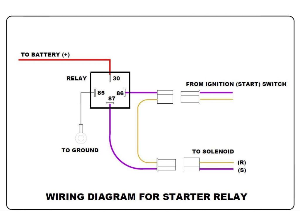
Alright folks, let's talk starter relay solenoid wiring diagrams. Understanding this diagram is crucial whether you're tackling a no-start condition, upgrading your electrical system, or just want a deeper grasp of how your car works. Consider this your guide to deciphering the often-intimidating world of automotive electrical schematics, specifically those relating to the starter system. We'll break down the components, symbols, and function so you can confidently troubleshoot and even modify your starter circuit.
Why Bother with the Diagram?
Why should you care about a wiring diagram? Simple. It’s the roadmap to your vehicle's electrical system. Think of it as the recipe for electricity to flow correctly to start your engine. Without it, diagnosing electrical problems is like searching for a needle in a haystack. Here's why a starter relay solenoid wiring diagram is essential:
- Troubleshooting No-Start Issues: The most common reason. If your car clicks but doesn't crank, or does absolutely nothing, the diagram helps you pinpoint whether the issue is a faulty relay, a wiring problem, a bad solenoid, or a problem further down the line.
- Component Replacement: Replacing a starter, solenoid, or relay? The diagram ensures you connect everything correctly, avoiding shorts and potential damage.
- System Upgrades and Modifications: Installing a new aftermarket starter? Adding a remote start system? The diagram shows you where to tap into the existing wiring safely and effectively.
- Learning Vehicle Electrical Systems: Understanding the starter circuit is a fundamental step in mastering automotive electrical systems. It teaches you about relays, solenoids, voltage drops, and current flow.
Key Specs and Main Parts
Before diving into the symbols and wiring, let's identify the key players in this electrical circuit. We'll need to understand their function for the diagram to make sense:
- Battery: The source of electrical power for the entire vehicle, including the starter system. Typically a 12-volt battery.
- Ignition Switch: The switch activated by your key. In the "start" position, it sends a signal to energize the starter relay.
- Starter Relay: An electromagnetic switch that allows a small current from the ignition switch to control a larger current flow to the starter solenoid. It protects the ignition switch from the high current draw of the starter.
- Starter Solenoid: A larger electromagnetic switch mounted on the starter. When energized, it does two things: it engages the starter motor pinion gear with the engine's flywheel (or flexplate) and it closes a high-current circuit to power the starter motor.
- Starter Motor: The electric motor that turns the engine over to initiate combustion.
- Ground (Chassis Ground): The return path for the electrical current, typically the vehicle's metal chassis.
- Fuses: Safety devices designed to protect the circuit from overloads. They are sacrificial devices that blow (open the circuit) when the current exceeds a specified limit.
Deciphering the Symbols
Wiring diagrams use standardized symbols to represent electrical components and wiring connections. Here's a breakdown of the most common symbols you'll encounter in a starter relay solenoid wiring diagram:
- Solid Lines: Represent wires. The thicker the line, the higher the current-carrying capacity of the wire.
- Dashed Lines: Often indicate wires that are optional or part of a sub-circuit. Sometimes they represent a ground connection.
- Circles: Can represent connectors, terminals, or bulbs (depending on the context).
- Rectangles: Usually represent components like relays, solenoids, or switches.
- Zigzag Line: Represents a resistor.
- Ground Symbol (Usually a series of horizontal lines decreasing in size): Indicates a connection to the vehicle's chassis ground.
- Battery Symbol (Alternating long and short lines): Represents the battery. The longer line represents the positive (+) terminal, and the shorter line represents the negative (-) terminal.
- Relay Symbol: Typically shows a coil (a looped symbol) and a set of contacts. The coil, when energized, pulls the contacts closed (or open, depending on the relay type).
- Colors: Wires are color-coded to aid in identification. Common colors include Red (power), Black (ground), Yellow, Blue, Green, White, and Brown. The diagram will usually include a color code legend.
Reading the Diagram: The diagram shows the electrical connections between these components. It doesn't necessarily represent the physical location of the components in the vehicle. The goal is to trace the path of electricity from the battery, through the ignition switch, relay, solenoid, and finally to the starter motor.
How It Works: A Step-by-Step Breakdown
- Turning the Key: When you turn the ignition key to the "start" position, the ignition switch closes a circuit, sending a small current to the starter relay's coil.
- Relay Activation: The current flowing through the relay's coil creates a magnetic field, which pulls the relay's contacts closed.
- Solenoid Power: Closing the relay contacts completes a high-current circuit from the battery (usually through a fuse) to the starter solenoid.
- Solenoid Engagement: The solenoid, now energized, performs two functions:
- It pushes the starter motor's pinion gear forward to engage with the engine's flywheel (or flexplate).
- It closes a heavy-duty switch, connecting the battery directly to the starter motor.
- Starter Motor Operation: The starter motor, receiving a large amount of current, begins to spin, turning the engine over.
- Releasing the Key: When you release the key, the ignition switch opens the circuit to the relay, de-energizing the solenoid and stopping the starter motor.
Real-World Use: Basic Troubleshooting
Okay, so your car won't start. How do you use the diagram to diagnose the problem? Here are a few basic troubleshooting steps:
- Check the Battery: Make sure the battery is fully charged and the terminals are clean and tight. Use a voltmeter to check the voltage; it should be around 12.6 volts with the engine off.
- Check the Fuses: Locate the fuse(s) associated with the starter circuit (consult your owner's manual or a vehicle-specific repair manual). Use a test light or multimeter to check for continuity. A blown fuse indicates a short circuit or overload.
- Listen for the Click: When you turn the key to the "start" position, listen for a "click" from the starter relay and the starter solenoid.
- No Click: Could indicate a faulty ignition switch, a bad relay, or a wiring problem between the switch and the relay. Use the diagram to trace the circuit and check for voltage at the relay coil terminals when the key is in the "start" position.
- Click from Relay, No Click from Solenoid: Could indicate a faulty relay (even though it clicks, the contacts might be burned), a wiring problem between the relay and the solenoid, or a faulty solenoid.
- Click from Both, No Crank: Could indicate a bad starter motor, a problem with the starter motor's ground connection, or a binding engine.
- Voltage Drop Testing: Use your multimeter to check for excessive voltage drops in the starter circuit. Excessive voltage drops indicate resistance in the circuit, which can prevent the starter from receiving enough power.
- Bypass the Relay: *Carefully* bypass the starter relay by jumping the terminals on the relay socket that connect to the solenoid. This allows you to directly power the solenoid and isolate a faulty relay. Warning: Only do this if you are comfortable working with electrical circuits and understand the risks.
Safety First!
Working with automotive electrical systems can be dangerous. Here are some important safety precautions:
- Disconnect the Battery: Before working on any electrical component, disconnect the negative (-) battery cable to prevent accidental shorts and shocks.
- Use Proper Tools: Use insulated tools designed for automotive electrical work.
- Avoid Working Alone: It's always a good idea to have someone nearby in case of an emergency.
- Be Aware of High Current: The starter circuit carries a very high current. Avoid touching exposed terminals or wires when the circuit is energized.
- Protect Yourself: Wear safety glasses and gloves to protect your eyes and hands.
- Never bypass fuses with wire or foil: This can create a fire hazard. Always use the correct amperage replacement fuse.
Mastering the starter relay solenoid wiring diagram isn't an overnight process. Take your time, study the diagram, and practice your troubleshooting skills. With a little patience and the right knowledge, you can confidently diagnose and repair starter system problems.
We have a detailed, downloadable PDF of a sample starter relay solenoid wiring diagram available. It includes color-coded wires and common troubleshooting points. It's a great resource to keep handy in your garage.