
Starter Solenoid Wiring Diagram Chevy
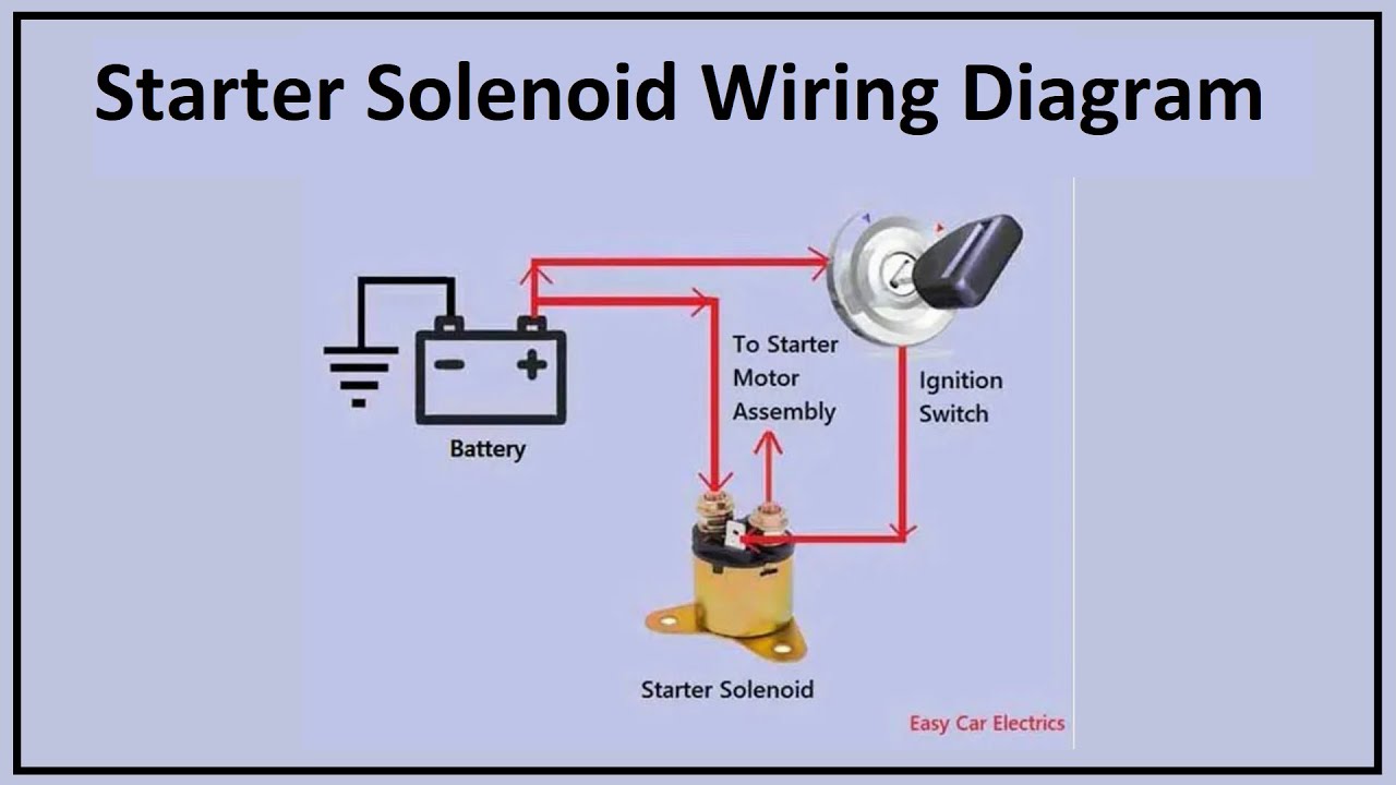
Understanding the starter solenoid wiring diagram for a Chevrolet vehicle is crucial for anyone tackling electrical repairs, performance modifications, or simply wanting a deeper understanding of their car's inner workings. Whether you're diagnosing a no-start condition, upgrading your electrical system, or just satisfying your curiosity, this knowledge will empower you to work on your Chevy with confidence. This article will delve into the intricacies of a typical Chevy starter solenoid wiring diagram, providing you with the knowledge to interpret it, troubleshoot common issues, and perform basic repairs.
Why This Diagram Matters
The starter system is responsible for cranking the engine, initiating the combustion process. A faulty starter solenoid can leave you stranded. The wiring diagram provides a roadmap for understanding how the various components of the starter system are connected, including the battery, ignition switch, solenoid, and starter motor. This allows you to:
- Diagnose Starting Problems: Pinpoint the source of a no-start condition or intermittent starting issues.
- Perform Electrical Repairs: Repair broken wires, replace faulty components, and ensure proper connections.
- Install Aftermarket Components: Integrate performance starters, remote start systems, or other electrical upgrades.
- Gain a Deeper Understanding: Comprehend the fundamental principles of automotive electrical systems.
Key Specs and Main Parts
Before diving into the diagram, it's important to understand the key components and their specifications. While specifics vary slightly by Chevy model and year, the fundamental principles remain consistent.
Main Parts:
- Battery: Provides the electrical power to the entire system (typically 12V DC).
- Ignition Switch: Activates the starter circuit when turned to the "start" position.
- Starter Solenoid: An electromagnetic switch that engages the starter motor and provides high current from the battery. Often mounted directly on the starter motor.
- Starter Motor: A powerful electric motor that cranks the engine to initiate combustion.
- Neutral Safety Switch (Automatic Transmissions): Prevents the engine from starting unless the transmission is in Park or Neutral. A Clutch Position Switch performs a similar function in Manual Transmissions.
- Wiring Harness: A collection of wires that connect the various components of the starter system.
- Fuses/Relays: Protect the electrical system from overloads and control the flow of current.
Key Specs (Typical Values):
- Battery Voltage: 12V DC (typically 12.6V when fully charged).
- Solenoid Activation Voltage: 12V DC (signal from the ignition switch).
- Starter Motor Current Draw: 100-200 Amps (during cranking). This can vary greatly depending on engine size and temperature.
- Wire Gauge: Varies depending on the circuit. The main battery cable to the starter solenoid is typically a heavy gauge (e.g., 4 AWG or larger) due to the high current draw. The solenoid activation wire is typically a smaller gauge (e.g., 16 AWG).
Decoding the Symbols
Wiring diagrams use standardized symbols to represent electrical components and connections. Understanding these symbols is essential for interpreting the diagram correctly.
- Lines: Represent wires. Thicker lines typically indicate higher current-carrying capacity.
- Colors: Indicate the color of the wire insulation. Color coding helps identify and trace wires within the harness. Common colors include red (power), black (ground), yellow, blue, green, and white.
- Circles with X: Represent lamps or bulbs (e.g., dashboard indicator lights).
- Rectangles: Can represent various components, including relays, switches, and control modules. The symbol will usually be labeled.
- Zigzag Line: Resistors.
- Ground Symbol: Indicates a connection to the vehicle's chassis ground (negative terminal of the battery). Usually depicted as stacked triangles.
- SPST/SPDT/DPST/DPDT: Represent different types of switches. These acronyms stand for Single Pole Single Throw, Single Pole Double Throw, Double Pole Single Throw, and Double Pole Double Throw, respectively. Understanding these switch types is crucial for understanding how the ignition switch and other switches control the starter circuit.
Additionally, the diagram will often include abbreviations to identify specific circuits and components. For example, "IGN" might stand for Ignition, "BAT" for Battery, and "SOL" for Solenoid. Always refer to the legend or key accompanying the diagram to understand the meaning of these abbreviations.
How It Works: Tracing the Circuit
The starting process begins when you turn the ignition key to the "start" position. This sends a 12V signal through the ignition switch to the starter solenoid. The solenoid acts as an electromagnetic switch.
- When energized, the solenoid's internal coil creates a magnetic field.
- This magnetic field pulls a plunger, which performs two key functions:
a) Engages the starter motor's drive pinion gear with the engine's flywheel or flexplate.
b) Closes a high-current contact, connecting the battery directly to the starter motor.
- The starter motor then cranks the engine.
- Once the engine starts, releasing the ignition key de-energizes the solenoid, disengaging the starter motor and disconnecting the battery.
The Neutral Safety Switch or Clutch Position Switch ensures that the circuit is only completed when the transmission is in Park/Neutral (automatic) or the clutch pedal is fully depressed (manual). This prevents the engine from starting accidentally while in gear.
Real-World Use: Basic Troubleshooting
The wiring diagram becomes invaluable when troubleshooting starting problems. Here are some basic troubleshooting steps:
- No Crank, No Click: Check the battery voltage. If it's low, charge or replace the battery. Also, check the ignition switch and wiring to the solenoid for continuity. Use a multimeter to verify that 12V is reaching the solenoid when the key is in the "start" position. Check fuses.
- No Crank, Click: The solenoid is engaging, but the starter motor isn't turning. This could indicate a faulty starter motor, a corroded battery cable connection, or a bad solenoid contact. Test the starter motor directly by applying 12V to the main terminal. If it doesn't turn, the starter motor is likely faulty.
- Slow Crank: Could be a weak battery, corroded battery cables, or a failing starter motor. Check the voltage drop across the battery cables while cranking the engine. Excessive voltage drop indicates a connection problem.
- Starter Stays Engaged: This is often a sign of a faulty solenoid. The contacts inside the solenoid may be sticking. Replace the solenoid.
Remember to use a multimeter to check for voltage and continuity in the circuit. Visually inspect wires for damage, corrosion, or loose connections. Clean corroded terminals with a wire brush and apply dielectric grease to prevent future corrosion.
Safety: Handle with Care
Working with automotive electrical systems can be dangerous. Always disconnect the negative battery cable before working on any electrical component. Be particularly careful when working with the starter solenoid and battery cables, as they carry high current.
Battery acid is corrosive and can cause burns. Wear appropriate safety glasses and gloves when working with batteries.
Never bypass the Neutral Safety Switch or Clutch Position Switch, as this can create a dangerous situation. Ensure the vehicle is properly secured (parking brake engaged) before performing any tests that require the engine to be cranked.
When working on the starter, be mindful of the potentially hot exhaust manifold nearby. Allow the engine to cool before working in that area to avoid burns.
By understanding the starter solenoid wiring diagram and following safe practices, you can effectively troubleshoot and repair your Chevy's starting system, saving you time and money.
We have a detailed Chevy Starter Solenoid Wiring Diagram file available for download. This comprehensive resource will provide you with the specific information you need for your vehicle. Contact us for access to the file.