
Starter Solenoid Wiring Diagram Ford
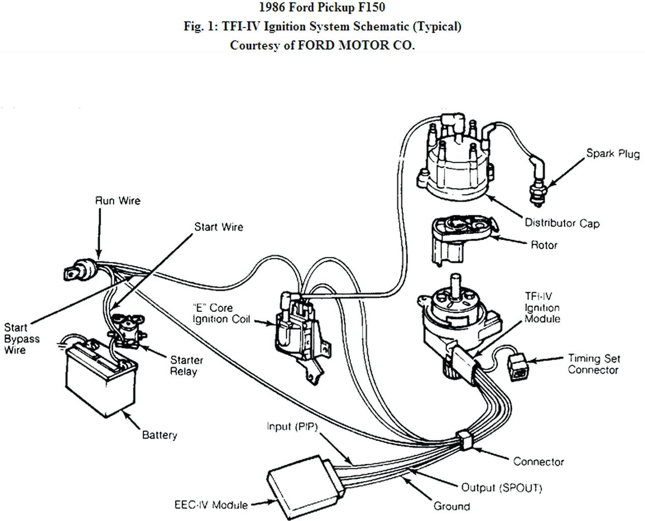
Understanding the starter solenoid wiring diagram in your Ford is crucial for anyone tackling electrical repairs, modifications, or even just general diagnostics. It provides a roadmap to how the starting system functions, enabling you to pinpoint problems quickly and efficiently. This article will break down a typical Ford starter solenoid wiring diagram, explaining the key components, their functions, and how to troubleshoot common issues.
Purpose of Understanding the Starter Solenoid Wiring Diagram
Why bother learning about this? The diagram is your key to:
- Repairing Starting Problems: Diagnosing a no-start condition is a common automotive headache. The wiring diagram helps you trace the electrical path, testing for voltage and continuity along the way to identify faulty components.
- Performing Electrical Modifications: Adding accessories or upgrading components requires a solid understanding of the existing wiring. The diagram ensures you're making safe and effective connections.
- Understanding Your Vehicle's Electrical System: Even if you're not actively repairing anything, knowing how the starting system works can give you valuable insights into your vehicle's overall electrical health.
- Avoiding Costly Mechanic Bills: With a bit of knowledge, you can often diagnose and fix simple starting problems yourself, saving money on labor costs.
Key Specs and Main Parts of the Starting System
Before diving into the diagram itself, let's define the key players:
- Battery: The source of electrical power for the entire system. Typically, a 12-volt battery is used.
- Ignition Switch: This switch, activated by the key, sends a signal to the solenoid to initiate the starting process.
- Starter Solenoid: This is an electromagnetic switch. It receives a low-current signal from the ignition switch and, in turn, closes a high-current circuit to the starter motor. In many Fords, the solenoid is mounted *on* the starter motor. Older models, however, frequently have a fender-mounted solenoid.
- Starter Motor: The electric motor that physically cranks the engine to start it. It requires a large amount of current to operate.
- Neutral Safety Switch (NSS) / Transmission Range Sensor (TRS): A safety device that prevents the engine from starting unless the transmission is in Park or Neutral. This prevents accidental starts while in gear. The name depends on the specific Ford model.
- Wiring Harness: A bundle of wires that connects all the components together.
- Fuses and Relays: Protective devices that prevent damage from overloads and help control high-current circuits with low-current signals, respectively.
Decoding the Starter Solenoid Wiring Diagram: Symbols, Lines, and Colors
Wiring diagrams use standardized symbols and conventions. Here's a breakdown:
- Lines: Lines represent wires. Their thickness often indicates the wire gauge (thicker lines usually mean thicker wires, carrying more current).
- Colors: Wires are color-coded to help identify them. The diagram will have a legend indicating what each color represents (e.g., Red = Battery +, Black = Ground, Yellow = Ignition). Standard automotive wire colors are typically used.
- Symbols: Symbols represent components like switches, solenoids, motors, fuses, and grounds. Common symbols include:
- Battery: A series of long and short parallel lines.
- Switch: A line that can be opened or closed to complete or break a circuit.
- Solenoid: A coil of wire wrapped around an iron core with a movable plunger.
- Motor: A circle with an "M" inside.
- Fuse: A zig-zag line enclosed in a rectangle.
- Ground: A series of downward-pointing triangles.
- Numbers and Letters: Numbers and letters are often used to identify specific wires, connectors, or terminals.
Example: A line colored "Red" might be labeled "+12V" or "BATT" to indicate it's connected to the positive terminal of the battery. A black line is generally labeled "GND" or using the ground symbol.
How the Ford Starter System Works: A Step-by-Step Explanation
Here's a simplified explanation of how the starting system operates, referencing the wiring diagram:
- Key in Ignition: When you insert the key and turn it to the "Start" position, you're activating the ignition switch.
- Signal to Solenoid: The ignition switch sends a low-current signal, typically through the Neutral Safety Switch (NSS) / Transmission Range Sensor (TRS), to the starter solenoid. The NSS/TRS ensures the car is in Park or Neutral before allowing the start signal to proceed.
- Solenoid Activation: The low-current signal energizes the solenoid's coil, creating an electromagnetic field. This field pulls in a plunger, which closes a heavy-duty electrical contact.
- High-Current to Starter: Closing the contact allows a high-current circuit from the battery to flow directly to the starter motor. This high current is what's needed to crank the engine.
- Starter Engages: The starter motor's spinning action engages with the engine's flywheel or flexplate, causing the engine to rotate.
- Engine Starts: Once the engine starts, you release the key, the ignition switch signal is cut off, the solenoid de-energizes, and the starter disengages.
Real-World Use: Basic Troubleshooting Tips Using the Wiring Diagram
Let's say your Ford won't start. Here's how the wiring diagram can help:
- No Click, No Crank:
- Check the battery voltage. Use a multimeter to ensure it's at least 12.4 volts.
- Inspect the wiring connections at the battery, solenoid, and starter for corrosion or looseness. Clean or tighten as needed.
- Use the wiring diagram to locate the Neutral Safety Switch. Test its continuity when the shifter is in Park/Neutral. If there's no continuity, the switch is likely faulty.
- Check the fuse for the starter circuit. Replace it if it's blown.
- Test the solenoid. Use a multimeter to check for voltage at the small terminal when the key is in the "Start" position. If there's no voltage, the problem is likely in the ignition switch or wiring leading to the solenoid.
- Clicking Sound, No Crank:
- This usually indicates a weak battery or a problem with the starter motor itself. Have the battery load tested.
- Check the high-current connections at the starter and solenoid. Corrosion can cause high resistance and prevent the starter from getting enough power.
- Starter Cranks Slowly:
- Again, a weak battery is a prime suspect.
- Check the starter motor's ground connection. A poor ground can restrict current flow.
Remember to always consult your specific vehicle's wiring diagram, as there may be slight variations depending on the year, make, and model.
Safety First: Highlighting Risky Components
The starting system involves high currents, so safety is paramount:
- Battery: Always disconnect the negative battery cable before working on the electrical system to prevent accidental shorts.
- High-Current Wires: Be extremely careful when working with the large-gauge wires connected to the starter and solenoid. These wires can carry hundreds of amps, which can cause severe burns or electrical shock.
- Short Circuits: Avoid creating short circuits. A short circuit can damage wiring, components, and even start a fire. Use insulated tools and be careful not to let wires come into contact with ground.
Caution: Working on your car's electrical system can be dangerous. If you are not comfortable performing these repairs, consult a qualified mechanic.
With this knowledge, you're well-equipped to understand and utilize a Ford starter solenoid wiring diagram for diagnosing and repairing starting system issues. Remember to always refer to the specific diagram for your vehicle and prioritize safety.
We have a sample Ford starter solenoid wiring diagram file available for download. This will provide a visual aid to help you better understand the concepts discussed in this article. Contact us to get the file.