Steering Column Ignition Switch Wiring Diagram Chevy
Let's dive into the intricate world of Chevy steering column ignition switch wiring diagrams. Whether you're wrestling with a no-start situation, planning a custom modification, or simply expanding your automotive know-how, understanding this diagram is crucial. It's the roadmap to your car's electrical startup system, and decoding it empowers you to diagnose problems, perform repairs, and even enhance functionality with confidence.
Purpose of the Ignition Switch Wiring Diagram
This wiring diagram serves several essential purposes. First and foremost, it's a troubleshooting tool. When your Chevy refuses to start, stalls unexpectedly, or exhibits electrical gremlins related to the ignition system, the diagram allows you to trace the circuit, identify potential fault points (like corroded connectors or broken wires), and pinpoint the source of the problem. Secondly, it's invaluable for electrical repairs. Need to replace a faulty ignition switch or repair damaged wiring? The diagram ensures you're connecting the correct wires in the right sequence. Finally, it's a foundation for custom modifications. If you're adding aftermarket accessories that integrate with the ignition system (like remote starters or security systems), the diagram shows you the critical circuits you need to tap into.
Key Specs and Main Parts
Before we delve into the specifics, let's identify the core components typically depicted in a Chevy steering column ignition switch wiring diagram:
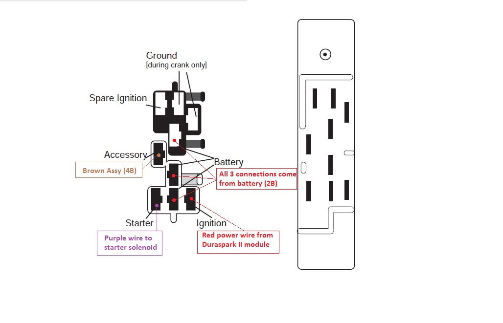
- Ignition Switch: This is the heart of the system, typically a multi-position switch that controls various electrical circuits based on the key position (Off, Accessory, Run, Start).
- Battery (BATT): The primary power source for the vehicle's electrical system.
- Starter Solenoid: An electromagnetic switch that engages the starter motor to crank the engine. It’s often labeled “S” on the ignition switch.
- Accessories (ACC): Circuits that power non-essential items like the radio, power windows, and climate control system.
- Run (IGN): Circuits that power the engine management system, fuel pump, and other critical components needed for the engine to run.
- Fuses and Relays: Protective devices that prevent overcurrent and control high-current circuits with low-current signals, respectively. They are crucial components and are identified by amp rating.
- Ground (GND): The return path for electrical current. Usually connected to the vehicle's chassis.
- Neutral Safety Switch (NSS) / Park/Neutral Position (PNP) Switch: Prevents the engine from starting unless the transmission is in Park or Neutral (automatic transmissions).
- Wiring Harness Connectors: Points where wires connect to components or other parts of the wiring harness. Often identified with alphanumeric codes.
Specific wire gauges (e.g., 12 AWG, 16 AWG) and fuse amperage ratings (e.g., 10A, 20A) are crucial specs found within the diagram. These determine the current-carrying capacity and protection level of each circuit.
Decoding the Symbols
Wiring diagrams rely on standardized symbols to represent components and connections. Here's a breakdown of the common symbols you'll encounter:
- Solid Lines: Represent wires. The thickness of the line *doesn't* typically indicate wire gauge, so always refer to the wire gauge markings (if provided).
- Dashed Lines: Often represent ground connections or shielded wires.
- Circles: Can represent terminal connections, splices in the wiring, or sometimes small components like diodes (depending on the diagram's detail).
- Squares/Rectangles: Usually represent components like switches, relays, or modules.
- Zigzag Lines: Represent resistors.
- Coils (Spirals): Represent inductors or relay coils.
- Color Codes: Each wire is assigned a color code (e.g., RED, BLU, GRN). These codes are *essential* for identifying the correct wire within a harness. Standard abbreviations are used.
Understanding color codes is paramount. Common abbreviations include:
- BLK: Black
- RED: Red
- BLU: Blue
- GRN: Green
- WHT: White
- YEL: Yellow
- BRN: Brown
- ORG: Orange
- PNK: Pink
- TAN: Tan
- GRY: Gray
Sometimes, you'll see a wire with a dual color code (e.g., RED/WHT). This means the wire is primarily red with a white stripe.
How It Works: Following the Circuit
The ignition switch is essentially a series of switches within a single housing. When you turn the key, you're activating different circuits in a specific sequence. Here's a simplified explanation:
- OFF: All circuits are de-energized (except, perhaps, a constant-on circuit for the clock or radio memory).
- ACCESSORY: The accessory circuit is energized, powering the radio, power windows, etc. The ignition circuit remains off.
- RUN (IGN): The accessory circuit remains energized, and the ignition circuit is energized. This powers the engine control unit (ECU), fuel pump, and other vital engine components. The engine is ready to start.
- START: The accessory circuit may be temporarily de-energized to provide maximum power to the starter motor. The ignition circuit remains energized. The starter solenoid is energized, engaging the starter motor to crank the engine. Once the engine starts, you release the key back to the RUN position.
The wiring diagram shows how each of these circuits is connected and protected. For instance, the START circuit will typically run through a dedicated fuse and a relay (if needed), then to the starter solenoid. The RUN circuit will power various sensors and actuators, and the diagram will show the fuses and relays protecting those components as well.
Real-World Use: Basic Troubleshooting Tips
Let's say your Chevy won't start. Here's how you can use the ignition switch wiring diagram:
- Check the Battery: Obvious, but essential. Ensure the battery has sufficient voltage (around 12.6 volts).
- Check Fuses: Using the diagram, locate the fuses associated with the ignition and starter circuits. Use a multimeter to check for continuity across each fuse. A blown fuse indicates a short circuit or overload.
- Check the Starter Solenoid: Locate the starter solenoid (usually on the starter motor). Use the diagram to identify the wire coming from the ignition switch (START circuit). Have someone turn the key to the START position while you check for voltage at that wire. If there's no voltage, the problem could be in the ignition switch, the wiring, or the neutral safety switch (if applicable).
- Check the Neutral Safety Switch (NSS): If your Chevy has an automatic transmission, the NSS prevents starting in any gear other than Park or Neutral. Use the diagram to locate the NSS and test its continuity in Park and Neutral. If it's faulty, the engine won't start.
- Inspect Wiring and Connectors: Visually inspect the wiring harness and connectors associated with the ignition switch. Look for corrosion, damaged insulation, or loose connections. Clean and repair as needed.
Example Scenario: You turn the key, and nothing happens – no clicks, no lights dimming. The diagram helps you verify that the START signal is reaching the starter solenoid. If it isn't, you can then trace the wiring back to the ignition switch and identify the break in the circuit. If the START signal is present, the problem likely lies with the starter solenoid itself or the starter motor.
Safety Considerations
Working on automotive electrical systems can be dangerous. Always disconnect the negative battery cable before working on any electrical components to prevent accidental shorts and potential fires. Be especially cautious when working around the ignition switch and starter solenoid, as these circuits carry high current. If you're not comfortable working with electricity, it's best to consult a qualified mechanic.
WARNING: Incorrect wiring can damage sensitive electronic components, leading to costly repairs. Double-check all connections before energizing the system. Always refer to the specific wiring diagram for your vehicle's year and model. Variations can exist even within the same model year.
Wrapping Up
Mastering the steering column ignition switch wiring diagram empowers you to diagnose and repair electrical issues with confidence. Remember to always prioritize safety, double-check your work, and refer to the specific diagram for your Chevy model. With a little patience and the right information, you can tackle many electrical repairs yourself.
We have a comprehensive wiring diagram file available for download to help you further. Happy wrenching!