Stereo 2000 Jeep Cherokee Radio Wiring Diagram
So, you're diving into the stereo system of a 2000 Jeep Cherokee, huh? Excellent choice. Whether you're replacing a busted head unit, upgrading your speakers, or simply tracing a wiring issue, a solid understanding of the radio wiring diagram is absolutely crucial. Consider this article your guide to navigating that diagram effectively.
Why This Diagram Matters
Let's be clear: blindly poking around with wires in your dashboard is a recipe for disaster. The 2000 Jeep Cherokee's wiring harness, while relatively simple, can still be confusing without a map. This wiring diagram is your map. It allows you to:
- Diagnose electrical problems in the radio circuit.
- Replace the factory head unit with an aftermarket one.
- Install amplifiers, subwoofers, and other audio accessories.
- Understand the overall electrical system of your Jeep.
Without it, you're essentially guessing, which can lead to short circuits, blown fuses, and even damage to sensitive electronic components. This is especially important because older vehicles like the 2000 Cherokee can suffer from brittle wiring and corroded connectors, making accurate troubleshooting even more critical.
Key Specs and Main Parts of the 2000 Cherokee Radio System
Before we delve into the diagram itself, let's establish some key specs and identify the main components you'll encounter:
Key Specs:
- Voltage: The system operates on a 12-volt DC (Direct Current) electrical system. This is the standard for automotive electronics.
- Speaker Impedance: Factory speakers are typically 4 ohms (Ω). This is important when choosing aftermarket speakers or amplifiers. Using speakers with the wrong impedance can damage your amplifier or head unit.
- Wiring Harness: The radio connects to the Jeep's electrical system via a specific wiring harness. Aftermarket adapters are readily available to simplify connecting a new head unit to this harness.
Main Parts:
- Head Unit (Radio): The central control unit for the audio system. It receives power, processes audio signals, and sends them to the speakers.
- Speakers: These convert the electrical audio signal into sound. The 2000 Cherokee typically has speakers in the front doors and possibly the rear sound bar (if equipped).
- Antenna: Receives radio signals. The antenna wire is usually a coaxial cable that connects to the back of the head unit.
- Wiring Harness: A collection of wires and connectors that connect the radio to the vehicle's electrical system. This includes power, ground, speaker wires, and potentially other signals like illumination and remote turn-on.
- Fuses: Protective devices that prevent overcurrent from damaging the electrical system. There's usually a dedicated fuse for the radio.
- Ground Connection: A secure connection to the vehicle's chassis, providing a return path for the electrical current. A poor ground connection can cause all sorts of audio problems.
Understanding the Diagram: Symbols, Lines, and Colors
A wiring diagram is essentially a symbolic representation of the electrical circuit. Here's a breakdown of the common symbols and conventions you'll find:
- Lines: Represent wires. The thickness of the line doesn't typically indicate wire gauge (size).
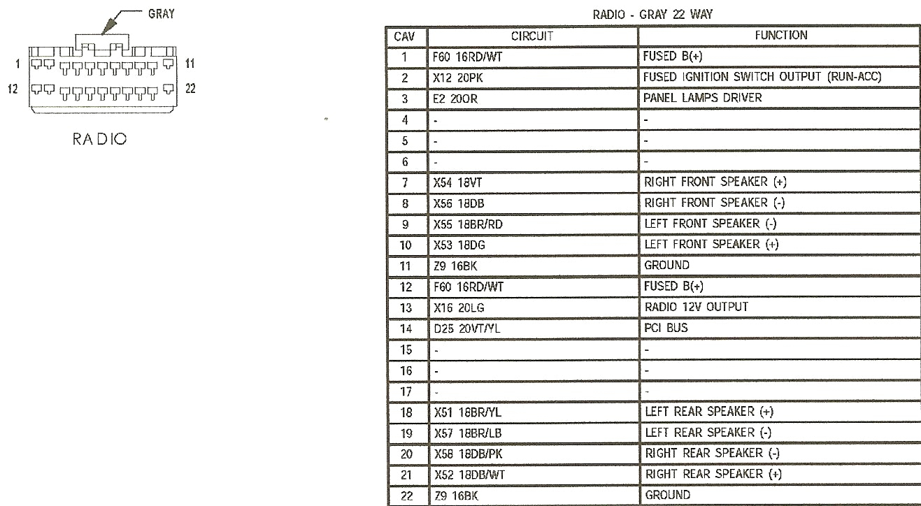
- Colors: Each wire is identified by a specific color code. This is crucial for tracing wires in the harness. Common colors include red (power), black (ground), and various colors for the speaker wires (e.g., white/gray, green/purple). The color code is usually abbreviated (e.g., RD for red, BK for black).
- Symbols for Components:
- Resistors: A zig-zag line.
- Capacitors: Two parallel lines.
- Ground: A series of lines getting progressively smaller, pointing downwards.
- Fuses: A line with a break in the middle, sometimes resembling a "C" shape.
- Connectors: Represented by circles or squares where wires connect.
Critical Note: Pay very close attention to the color codes. Manufacturers sometimes use slightly different shades, so work in good lighting and double-check your connections.
How the 2000 Cherokee Radio System Works (Simplified)
The radio system's operation is relatively straightforward:
- Power: The head unit receives power from the vehicle's battery through the ignition switch (switched power) and directly from the battery (constant power). The switched power turns the radio on and off with the ignition, while the constant power maintains memory settings like radio presets.
- Antenna Signal: The antenna receives radio signals and sends them to the head unit.
- Signal Processing: The head unit processes the audio signal from the antenna (or CD player, if equipped) and amplifies it.
- Speaker Output: The amplified audio signal is sent to the speakers through dedicated speaker wires.
- Ground: Each component, especially the head unit, needs a good ground connection to complete the electrical circuit.
The wiring diagram visually represents this flow of electricity and signal, allowing you to trace the path from the power source to the speakers.
Real-World Use: Basic Troubleshooting Tips
Here are a few common problems and how the wiring diagram can help you troubleshoot them:
- No Power to Radio:
- Check the radio fuse. The diagram will show you which fuse to check.
- Verify that the head unit is receiving both switched and constant power using a multimeter. Use the wiring diagram to identify the correct wires.
- Check the ground connection. A loose or corroded ground can cause a complete loss of power.
- No Sound from Speakers:
- Check the speaker wires. Make sure they are securely connected to both the head unit and the speakers. The diagram will show you the correct wire colors for each speaker.
- Test the speakers themselves. Use a multimeter to check for continuity.
- If you've recently installed a new head unit, double-check that you've connected the speaker wires correctly according to the aftermarket adapter's wiring diagram.
- Humming or Static:
- Check the ground connection. This is often the culprit.
- Check the antenna connection. A loose or corroded antenna connection can introduce noise.
- Inspect the speaker wires for damage.
Safety First!
Working with automotive electrical systems can be dangerous. Here are some key safety precautions:
- Disconnect the Battery: Always disconnect the negative terminal of the battery before working on any electrical components. This prevents accidental short circuits.
- Use a Multimeter: A multimeter is your best friend. It allows you to safely measure voltage, current, and resistance. Learn how to use it properly.
- Insulate Exposed Wires: Use electrical tape or heat shrink tubing to insulate any exposed wires.
- Be Careful with Fuses: Never replace a fuse with one of a higher amperage rating. This can overload the circuit and cause a fire.
- Consult a Professional: If you're not comfortable working with electrical systems, don't hesitate to consult a qualified mechanic or car audio installer.
Important Safety Tip: The airbag system is also wired in the dashboard area. Be extremely careful not to tamper with any wires related to the airbags, as accidental deployment can cause serious injury.
By understanding the 2000 Jeep Cherokee radio wiring diagram, you can confidently tackle a variety of audio-related projects and repairs. Remember to work safely, take your time, and double-check your connections.
And guess what? We have the complete, high-resolution wiring diagram ready for you to download. It's a valuable resource that will make your troubleshooting and installation projects much easier. Good luck, and happy tinkering!