Stereo Wiring Harness For 2004 Chevy Trailblazer
If you're planning to upgrade the stereo in your 2004 Chevy Trailblazer, troubleshoot audio problems, or even just understand your vehicle's electrical system better, understanding the stereo wiring harness is crucial. This article provides a detailed technical overview of the 2004 Trailblazer's stereo wiring, assuming a working knowledge of basic automotive electronics and tools. We'll cover the purpose, key specifications, how the system works, real-world troubleshooting, and essential safety considerations. We have the wiring diagram available for download, which will be an invaluable resource as you work.
Purpose of Understanding the Wiring Harness
Why bother digging into the wiring? There are several key reasons:
- Aftermarket Stereo Installation: Installing a new head unit (the main stereo unit) almost always requires adapting the factory wiring harness to the new stereo's connectors. Knowing the function of each wire prevents damage and ensures proper functionality.
- Troubleshooting Audio Problems: If you're experiencing issues like no sound, distorted audio, or speaker malfunctions, understanding the wiring can help you isolate the problem to specific circuits or components.
- System Upgrades: Adding amplifiers, subwoofers, or other audio enhancements requires tapping into the existing wiring, and knowing what each wire does is paramount.
- General Automotive Electrical Knowledge: Understanding the stereo wiring harness provides a foundation for comprehending more complex automotive electrical systems.
- Repairing Damaged Wiring: Over time, wiring can become damaged due to age, wear and tear, or accidental damage. Identifying the correct wires for repair is critical.
Key Specs and Main Parts
The 2004 Chevy Trailblazer's stereo system is a relatively standard setup for its time. Key specifications and main parts include:
- Voltage: 12V DC (Direct Current) - This is the standard voltage for automotive electrical systems.
- Ground: Chassis Ground - The negative terminal of the battery is connected to the vehicle's frame, providing a common ground point for all electrical components.
- Head Unit: The main control unit for the stereo system, responsible for processing audio signals and controlling various functions. The factory head unit typically incorporates an AM/FM tuner, CD player (depending on the trim level), and potentially cassette deck.
- Speakers: Typically, the Trailblazer has speakers in the front doors (tweeters and woofers often separate), rear doors (or side panels), and sometimes a subwoofer (depending on the trim level and optional packages).
- Amplifier (Optional): Some Trailblazer models came with a factory amplifier, usually located under the rear seat or in the rear cargo area. This amplifier boosts the audio signal before it's sent to the speakers.
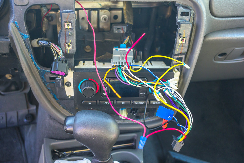
- Wiring Harness: The collection of wires and connectors that connect the head unit to the vehicle's electrical system and the speakers. The main harness plugs directly into the back of the head unit. There may also be a separate harness for the amplifier (if equipped).
- Antenna: Receives radio signals.
The most important part for our discussion is the wiring harness itself. This bundle of wires plugs into the back of the head unit and distributes power, ground, and audio signals to the speakers. Understanding the function of each wire in the harness is essential for any modification or repair.
Symbols and Color Codes in the Wiring Diagram
The wiring diagram uses specific symbols and color codes to represent different components and wires. Here's a breakdown:
- Lines: Solid lines represent wires. Dashed lines may represent shielded cables or connections within a component.
- Colors: Each wire is identified by a specific color or color combination (e.g., Red, Black, White/Blue). These color codes are standardized and are usually consistent across different GM vehicles of the same era.
- Icons: Icons represent components like speakers, fuses, relays, and the head unit itself. These icons are typically stylized representations of the physical components.
- Wire Gauge: The diagram may also indicate the wire gauge (thickness) using AWG (American Wire Gauge) numbers. Lower AWG numbers indicate thicker wires, which can carry more current.
Common wire color codes in GM vehicles of this era include:
- Red: Typically indicates a constant 12V power source.
- Yellow: Typically indicates a switched 12V power source (power is only available when the ignition is on).
- Black: Ground.
- White: Often used for speaker wires.
- Green, Blue, Brown, Gray, Purple: These colors are frequently used for speaker wires, often with a stripe of another color to differentiate between different speaker channels (e.g., Left Front +, Left Front -, Right Front +, etc.).
Important Note: While these color codes are common, always verify the wire's function using the wiring diagram and a multimeter before making any connections.
How It Works: The Audio Signal Path
The audio signal path starts with the head unit. Here's a simplified overview:
- Power and Ground: The head unit receives power from the vehicle's battery (via the constant and switched 12V wires) and connects to the chassis ground.
- Source Selection: The user selects the audio source (e.g., AM/FM radio, CD player).
- Signal Processing: The head unit processes the audio signal from the selected source. This may involve amplifying the signal, adjusting the tone (bass, treble), and applying other audio effects.
- Output: The processed audio signal is sent to the speakers through the wiring harness. If the vehicle has a factory amplifier, the signal is sent to the amplifier first, which further boosts the signal before sending it to the speakers.
- Speaker Output: Each speaker receives a positive (+) and negative (-) wire from the head unit (or amplifier). These wires carry the amplified audio signal, which causes the speaker cone to vibrate and produce sound.
The wiring harness acts as the critical intermediary, ensuring that the correct signals reach the correct components. A faulty wire or connection in the harness can disrupt the audio signal path and cause various problems.
Real-World Use: Basic Troubleshooting Tips
Here are some basic troubleshooting tips using the wiring diagram:
- No Power to Head Unit: Check the constant and switched 12V wires using a multimeter. Ensure that they are receiving the correct voltage. Also, check the ground wire for proper continuity to the chassis. Consult the wiring diagram to locate the fuses associated with the radio and verify that the fuses are intact.
- No Sound from One Speaker: Check the speaker wires for that particular speaker. Ensure that the wires are properly connected to the head unit (or amplifier) and the speaker. Use a multimeter to check the continuity of the speaker wires. A break in the wire can cause a loss of sound.
- Distorted Sound: Check the speaker wires for shorts to ground. A short to ground can cause the audio signal to become distorted. Also, check the speaker itself for damage.
- Ground Loop Hum: This can be caused by multiple ground points in the audio system. Try grounding the head unit and amplifier to the same point on the chassis.
- Intermittent issues: Loose connections are the most common cause of these. Inspect the harness connectors, look for corrosion, and try reseating the connectors. Gently wiggle the wires near the connector to see if this causes the problem to appear.
Remember: Always disconnect the negative terminal of the battery before working on the electrical system to prevent shorts and potential damage.
Safety Considerations
Working with automotive electrical systems can be dangerous. Here are some important safety considerations:
- Disconnect the Battery: Always disconnect the negative terminal of the battery before working on the electrical system. This prevents accidental shorts and potential damage to the vehicle's electronics.
- Work in a Well-Lit Area: Ensure that you have adequate lighting to see what you're doing.
- Use Proper Tools: Use insulated tools to prevent electrical shocks.
- Identify Wires Correctly: Always verify the function of each wire using the wiring diagram and a multimeter before making any connections. Never rely solely on color codes, as they can sometimes be misleading.
- Be Careful with Airbags: The stereo wiring harness is often located near airbag components. Avoid disturbing or damaging any airbag wiring, as this could cause the airbags to deploy unexpectedly. If you're unsure about how to handle airbag wiring, consult a qualified technician.
- Avoid cutting into factory wiring: Use adapters that plug into the factory harness. This will avoid potential damage to factory components and will also allow you to easily return the system to stock if needed.
The constant 12V wire is especially risky because it is always powered, even when the ignition is off. Accidental contact with the chassis can cause a short circuit and potentially damage the vehicle's electrical system.
By understanding the purpose, components, symbols, and operation of the 2004 Chevy Trailblazer's stereo wiring harness, you'll be well-equipped to tackle stereo upgrades, troubleshoot audio problems, and gain a deeper understanding of your vehicle's electrical system. Remember to always prioritize safety and use the wiring diagram as your guide.
We have the complete wiring diagram file available for you. Please download it for a detailed view and reference while working on your Trailblazer's audio system.